Advertisement
Quick Links
Steampunk Bay
®
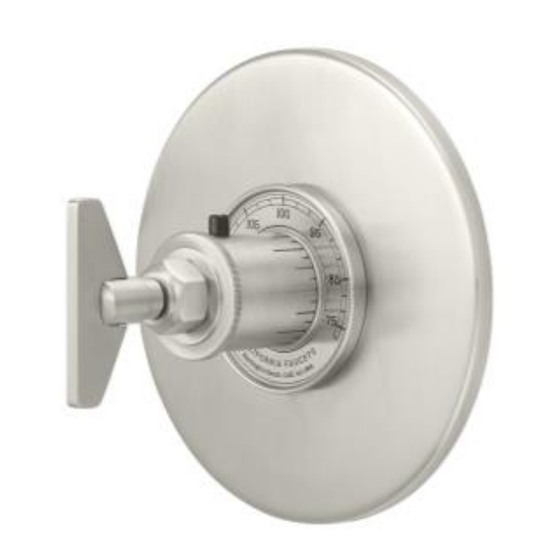
TO-THN-85 & TO-THQN-85
¾" Thermostatic Valve Trim
Installation Instructions
CALIFORNIA FAUCETS RECOMMENDS THAT ALL PLUMBING PRODUCTS BE INSTALLED
BY A LICENSED PROFESSIONAL
TO-THQN-85W
TO-THN-85
TO-THN-85B
TO-THN-85W
TO-THQN-85
TO-THQN-85B
IMPORTANT: Instructions to the Installer
Please read these instructions, fill in blanks below, and then give
these instructions to the end user.
WARNING: Risk of Scalding
This valve MUST have the TEMPERATURE SETTING verified during
installations. The INSTALLER is responsible for installing the valve
and setting of water temperature in accordance with these
instructions.
THIS THERMOSTATIC VALVE HAS BEEN PRESET
BY
OF
TH75-R
(ROUGH)
TO A MAXIMUM DISCHARGE TEMPERATURE OF ______°F.
ANY CHANGES TO THIS SETTING MAY INCREASE THE
DISCHARGE TEMPERATURE AND COULD RISK SCALDING OF
END USER.
DATE
CAUTION: Danger of scald injury.
Valve can be
recalibrated to provide higher temperature water. This valve has been
preset at the factory to provide a range of water temperatures. Any
change in settings or water inlet conditions from those used during
calibration at the factory may raise the outlet temperature and may
cause scalding. The responsibility for the proper installation and any
recalibration of this valve lies with the installer.
TO-THN-85_ii_210315
Pg 1
Advertisement

Related Manuals for California Faucets TO-THN-85


Summary of Contents for California Faucets TO-THN-85
- Page 1 Steampunk Bay ® TO-THN-85 & TO-THQN-85 ¾” Thermostatic Valve Trim Installation Instructions CALIFORNIA FAUCETS RECOMMENDS THAT ALL PLUMBING PRODUCTS BE INSTALLED BY A LICENSED PROFESSIONAL TO-THQN-85W TO-THN-85 TO-THN-85B TO-THN-85W TO-THQN-85 TO-THQN-85B IMPORTANT: Instructions to the Installer Please read these instructions, fill in blanks below, and then give these instructions to the end user.
- Page 2 REMOVING MUDGUARD • Remove MUDGUARD SCREW (4), WASHER (3) and MUDGUARD (2) from installed VALVE (1) • Slide plastic TEMPERATURE LIMIT STOP (6) onto thermostatic CARTRIDGE (5) with thin wall positioned slightly before 12 o’clock as shown • Temporarily place BONNET (7) onto thermostatic cartridge STEM (5a) Front view of TEMPERATURE LIMIT STOP...
- Page 3 INSTALLING TRIM WARNING: If distance between finish wall & end of CARTRIDGE NUT (10) is less than 1-5/16”, an extension kit (not included) MUST be used; DO NOT loosen CARTRIDGE NUT (10) to extend length as this will cause valve to not operate properly & lead to possible Finished Wall flood Note: Remove clear PROTECTIVE FILM (9b) from DIAL (9a) prior...
- Page 4 MAINTENANCE The thermostatic cartridge has built-in screens to prevent debris from affecting proper operation of anti- scald protection. Debris may build up on screens which will affect water flow and require occasional service. Thermostatic Cartridge Service • Loosen HANDLE (12a) remove HANDLE (12), SCREW (11), BONNET (7), SLEEVE (10) and FACEPLATE (9)
Need help?
Do you have a question about the TO-THN-85 and is the answer not in the manual?
Questions and answers