Advertisement
Available languages
Available languages
Quick Links
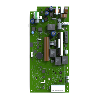
Logic Board
Model 041DJ003MC
Also replaces 050DCRJWF
NOTE:
Please read these instructions as programming may be different from older
programming.
To prevent possible SERIOUS INJURY or DEATH:
• Disconnect ALL electric and battery power BEFORE performing ANY
service or maintenance.
To prevent damage to the receiver/logic board, DO NOT touch printed
circuit board of replacement receiver/logic board during installation.
ALWAYS wear protective gloves and eye protection when changing the
battery or working around the battery compartment.
WARNING: This product can expose you to chemicals
including lead, which are known to the State of California to
cause cancer or birth defects or other reproductive harm.
For more information go to www.P65Warnings.ca.gov.
NOTICE: This device complies with Part 15 of the FCC rules and Industry
Canada's license-exempt RSSs. Operation is subject to the following two
conditions: (1) this device may not cause harmful interference, and (2)
this device must accept any interference received, including interference
that may cause undesired operation.
Any changes or modifi cations not expressly approved by the party
responsible for compliance could void the user's authority to operate the
equipment.
This device must be installed to ensure a minimum 20 cm (8 in.) distance
is maintained between users/bystanders and device.
This device has been tested and found to comply with the limits for a
Class B digital device, pursuant to part 15 of the FCC rules and Industry
Canada ICES standard. These limits are designed to provide reasonable
protection against harmful interference in a residential installation. This
equipment generates, uses and can radiate radio frequency energy and,
if not installed and used in accordance with the instructions, may cause
harmful interference to radio communications. However, there is no
guarantee that interference will not occur in a particular installation. If
this equipment does cause harmful interference to radio or television
reception, which can be determined by turning the equipment off and on,
the user is encouraged to try to correct the interference by one or more of
the following measures:
•
Reorient or relocate the receiving antenna.
•
Increase the separation between the equipment and receiver.
•
Connect the equipment into an outlet on a circuit different from that
to which the receiver is connected.
•
Consult the dealer or an experienced radio/TV technician for help.
Before you begin.
Your new myQ
®
serial number is located on the
replacement label with your replacement logic board. You will need this new myQ
serial number to connect your opener to the network.
1.
Disconnect power.
3.
Remove the battery cover.
Disconnect the battery. Remove
the battery and set aside (B).
4.
Disconnect the wires coming
from the safety reversing sensors,
door control, door lock and cable
tension monitor from the logic
board (C).
5.
Remove the logic board cover (D).
1
2.
Open the front panel (A).
8.
Install the new logic board and
connect the wiring harnesses. Route
the antenna through the channel in
the new battery cover.
9.
Adhere the new myQ serial number
label over the original label on the
logic board cover.
10.
Set door profile for new replacement
logic board. See page 2 to set door
profile steps.
11.
Reprogram the travel and test the
safety reversal system (see pages 2
6.
and 3).
Disconnect all the wiring harnesses
12.
from the logic board (E).
Program all remote controls and
7.
keyless entries (see page 4).
Remove the four screws securing
13.
the logic board, remove the logic
Use the myQ app to add the new
board (F), and discard.
myQ serial number to your account.
Battery Status LED
Red wire (+)
Black wire (-)
NOTE:
Be sure the short antenna is not pinched by the battery door and held in place
as shown.
Antenna
Advertisement

Related Manuals for Chamberlain 041DJ003MC


Summary of Contents for Chamberlain 041DJ003MC
- Page 1 Before you begin. Your new myQ ® serial number is located on the Model 041DJ003MC replacement label with your replacement logic board. You will need this new myQ serial number to connect your opener to the network. Also replaces 050DCRJWF Disconnect power.
- Page 2 Adjustment Set Door Profile Identify Door Profile To enter Set Door Profile mode, press and hold the black button for one second. The UP and DOWN buttons turn a solid color. To identify the door profile number, measure the full drum diameter based To prevent possible SERIOUS INJURY or DEATH, follow instructions to To set Door Profile, press the UP and DOWN buttons.
- Page 3 Adjustment Program the Travel Button Travel limits regulate the points at which the door will stop when moving up or down. Adjustment Button While programming the travel, the UP and DOWN buttons can be used to To prevent possible SERIOUS INJURY or DEATH, after ANY changes to move the door as needed.
- Page 4 Adjustment Test the Safety Reversal System With the door fully open, place a 1-1/2 inch (3.8 cm) board (or a 2x4 laid flat) on the floor, centered under the garage door. Press the remote control push button to close the door. The door Without a properly installed safety reversal system, persons MUST reverse when it makes contact with the board.
- Page 5 Programming Remote Control Your remote control has been programmed at the factory to operate with your garage door opener. If the remote does not work or you would like to program additional devices, follow the programming steps below. Up to 40 Security+ 2.0 remote controls can be programmed to the garage door opener.
- Page 8 © 2023, The Chamberlain Group LLC All rights reserved 114-5902-000...
-
Page 9: Avant De Commencer
Avant de commencer. Votre nouveau numéro de série myQ ® Modèle 041DJ003MC trouve sur l’étiquette de remplacement de la carte logique. Vous aurez besoin de ce nouveau numéro de série myQ pour connecter votre ouvre-porte au réseau. Remplace également 050DCRJWF Coupez le courant. - Page 10 Réglage Identifier le profil de la porte Identifier le profil de la porte Pour entrer dans le mode Identifier le profil de la porte, appuyez sur le bouton noir et maintenez-le enfoncé pendant une seconde. Les Pour identifier le numéro du profil de la porte, mesurez le diamètre complet Pour éviter tout risque de BLESSURE GRAVE voire MORTELLE, suivez boutons vers le HAUT et le BAS prennent une couleur unie.
- Page 11 Réglage Programmer le déplacement Bouton vers Les limites de déplacement règlent les points auxquels la porte s’arrête le HAUT lorsqu’elle monte ou descend. Bouton de Pendant la programmation de la course, les boutons fléchés vers le HAUT et Pour éviter des blessures graves voire mortelles, reprogrammez les réglage le BAS peuvent être utilisés pour déplacer la porte selon les besoins.
- Page 12 Réglage Faites un test pour vérifier le système d’inversion de sécurité. La porte étant complètement ouverte, placez une planche de 1,5 po (3,8 cm) ou un 2x4 posé à plat, centré(e) sous la porte du garage. Si le capteur d’inversion de sécurité n’est pas installé correctement, les Appuyez sur le bouton poussoir de la télécommande pour fermer la personnes (en particulier les jeunes enfants) peuvent SUBIR DES porte.
- Page 13 Programmation Télécommande La télécommande a déjà été programmée en usine pour fonctionner avec votre ouvre-porte de garage. Si la télécommande ne fonctionne pas ou si vous souhaitez programmer d’autres appareils, suivez les étapes de programmation ci-dessous. Jusqu’à 40 télécommandes Security+ 2.0 peuvent être programmées sur l’ouvre-porte de garage.
- Page 16 © 2023, The Chamberlain Group LLC Tous droits réservés 114-5902-000...
-
Page 17: Antes De Empezar
El número de serie de su nuevo myQ ® se encuentra Modelo 041DJ003MC en la etiqueta de reemplazo con su tarjeta lógica de reemplazo. Necesitará este nuevo número de serie de myQ para conectar su abrepuertas a la red. También reemplaza al modelo 050DCRJWF Desconecte la alimentación. - Page 18 Ajuste Establecimiento del perfil de la puerta Identificación del perfil de la puerta Para entrar en el modo Set Door Profile (Establecer el perfil de la puerta), mantenga presionado el botón negro durante un segundo. Los Para identificar el número de perfil de la puerta, mida el diámetro completo Para evitar posibles LESIONES GRAVES o la MUERTE, siga las botones UP (SUBIR) y DOWN (BAJAR) se vuelven de color constante.
- Page 19 Ajuste Programación del recorrido Botón UP Los límites de recorrido regulan los puntos en los cuales se detendrá la (SUBIR) puerta al moverse hacia arriba y hacia abajo. Botón Mientras programa el desplazamiento, los botones UP (SUBIR) y DOWN Para evitar posibles LESIONES GRAVES o la MUERTE, después de Adjustment (BAJAR) se pueden usar para mover la puerta según sea necesario.
- Page 20 Ajuste Prueba del Sistema de inversión de seguridad Con la puerta completamente abierta, coloque una tabla de 1-1/2 in (3.8 cm) (o una madera de 2x4 colocada horizontalmente) sobre el piso, centrada debajo de la puerta del garaje. Sin un sistema de inversión de seguridad instalado de forma correcta, Presione el botón Push (Pulsar) del control remoto para cerrar la las personas (en particular, los niños pequeños) podrían sufrir puerta.
-
Page 21: Control Remoto
Programación Control remoto El control remoto ya se programó en la fábrica para que funcione con su abrepuertas de garaje. Si el control remoto no funciona o desea programar dispositivos adicionales, siga los pasos de programación indicados a continuación. Se pueden programar hasta 40 controles remotos Security+ 2.0 ®... - Page 24 © 2023, The Chamberlain Group LLC Todos los derechos reservados 114-5902-000...
Need help?
Do you have a question about the 041DJ003MC and is the answer not in the manual?
Questions and answers