Table of Contents
Advertisement
Available languages
Available languages
Quick Links
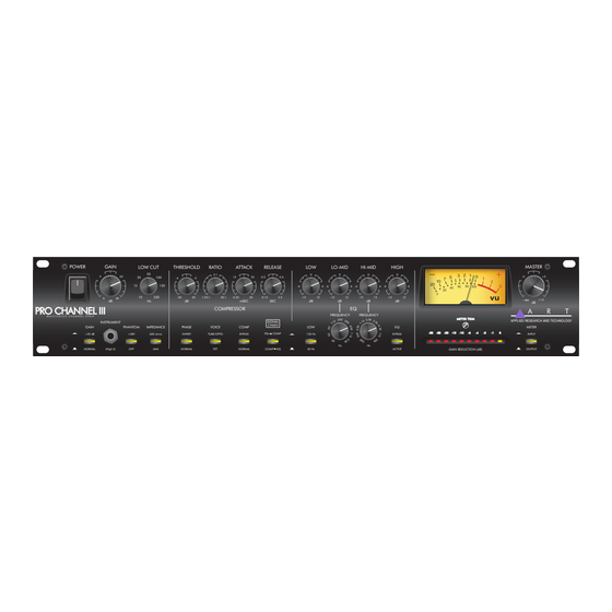
PRO CHANNEL III
POWER
GAIN
LOW CUT
50
9
20
25
15
10
0
40
dB
Hz
PRO CHANNEL III
PRO CHANNEL III
M U L T I V O I C E C H A N N E L S T R I P
INSTRUMENT
GAIN
PHANTOM
IMPEDANCE
+20 dB
+48V
600 ohms
NORMAL
(High Z)
OFF
User's Manual
Manuel de L 'Utilisation
M U L T I V O I C E C H A N N E L S T R I P
THRESHOLD
RATIO
ATTACK
RELEASE
3:1
100
12
25
0.3
-6
-2
150
250
-30
20
1.25:1
20:1
0.25
50
0.15
dB
mSEC
SEC
COMPRESSOR
SIGNAL
CHAIN
PHASE
VOICE
COMP
INVERT
TUBE/OPTO
BYPASS
EQ
MAX
NORMAL
FET
NORMAL
COMP
APPLIED RESEARCH AND TECHNOLOGY
LOW
LO-MID
HI-MID
0
0
0
0.6
-6
6
-6
6
-6
6
-6
3.0
-12
12
-12
12
-12
12
-12
dB
dB
dB
EQ
FREQUENCY
FREQUENCY
LOW
COMP
120 Hz
Hz
Hz
EQ
40 Hz
HIGH
0
6
12
dB
M E T E R T R I M
M E T E R T R I M
EQ
-30
-30
-25
-25
-20
-20
-15
-15
-10
-10
-6 -6
-4 -4
-2 -2
-1 -1
0 0
BYPASS
ACTIVE
GAIN REDUCTION (dB)
MASTER
-5
+5
-
+15
dB
APPLIED RESEARCH AND TECHNOLOGY
METER
INPUT
OUTPUT
MODEL 215
PROCHANNELIII
Advertisement
Table of Contents

Related Manuals for Art PRO CHANNEL III


Summary of Contents for Art PRO CHANNEL III
- Page 1 APPLIED RESEARCH AND TECHNOLOGY PRO CHANNEL III M U L T I V O I C E C H A N N E L S T R I P POWER GAIN LOW CUT THRESHOLD RATIO ATTACK RELEASE LO-MID HI-MID HIGH MASTER 1.25:1...
-
Page 2: Important Safety Instructions - English
• Do not install this apparatus in a confined more than the specified values of lead or something like that to prevent them from space such as a book case or similar unit. contacting other batteries or metallic objects. DOC-ART-Safety-AC-Eng-Fre-00-1v1 • November 14 17/2023... -
Page 3: Important Safety Instructions - Français
Important Safety Instructions - Français FRANÇAIS INSTRUCTIONS DE SÉCURITÉ IMPORTANTES ATTENTION: POUR RÉDUIRE LE RISQUE D’ÉLECTROCUTION, NE RETIREZ PAS LE CAPOT (OU L’ARRIÉRÉ). AUCUNE PIÈCE INTERNE N’EST RÉPARABLE PAR L’UTILISATEUR. CONFIEZ TOUTE RÉPARATION A UN SERVICE APRÈS-VENTE QUALIFIÉ. Le symbole d’éclair à tête de flèche dans un triangle équilatéral sert a prévenir l’utilisa- Le point d’exclamation dans un triangle équilatéral sert à... -
Page 4: Compliance Class-B
Compliance Class-B This equipment has been tested and found to comply with the limits • Connect the equipment into an outlet on a circuit different from for a Class B digital device, pursuant to part 15 of the FCC Rules. that to which the receiver is connected. -
Page 5: Table Of Contents
6. Power Connection ...............6 Block Diagram ................15 Applications ..................7 Warranty / Service - English ............16 Bypassing of The Pro Channel III ...........7 La Garantie/L’Entretien - Français ..........17 Optimization for Lowest Noise ..........7 Rear Page ..................18... -
Page 6: Introduction
’plosives’ can be reduced or possibly eliminated. The Instrument jack on the front panel allows direct access to the Pro Channel III and it’s use as a great DI. Using the front instrument input overrides the rear jacks allowing you to keep the microphone or line signal patched in. -
Page 7: Installation
AC Power Hookup The ART Pro Channel III has an internal power supply, only connect the unit to mains power of the type marked on the rear pan- el. The power source must provide a good ground connection and the ground pin on the mains plug should never be defeated. -
Page 8: Instrument Input
8. Threshold Control The THRESHOLD control sets the level which the compressor in the Pro Channel III starts to react on the input signal. As the control is turned clockwise, more input signal is needed to begin reducing gain. The compression action can be seen in the Gain Reduction LED meter. -
Page 9: Voice Switch
EQ section first then the Compressor section. 16. Semi-Parametric EQ / Low Switch The Pro Channel III offers a four-band semi-parametric equalizer. The entire EQ can be bypassed with a single switch. Each band has +/- 12dB of control range. -
Page 10: Rear Panel Connections
2. Output Jacks The analog output of the Pro Channel III is available on both a 1/4-inch balanced jack and an XLR balanced jack. Both outputs are active balanced and will adjust to balanced or unbalanced termination without gain change like a real trans- former output. -
Page 11: Applications
• To bypass the EQ: Use the EQ bypass switch. Optimization for Lowest Noise The preamp of the Pro Channel III can be optimized for low noise by combining use of the GAIN switch (Input CLIP) and Input GAIN control for microphone and line level signals. -
Page 12: Introduction
(HPF), le bruit du vent et les « plosives » peuvent être réduits, ou éliminés. La prise Instrument sur le panneau avant permet un accès direct au Pro Channel III et peut être utilisée comme une excellente DI. L’utilisation de l’entrée instrument avant remplace les prises arrière, vous permettant ainsi de con- server le signal du microphone ou de la ligne branché. -
Page 13: Installation
Commandes de Préampli Mic L’entrée Pro Channel III se compose d’un préampli différentiel discret de classe A. Le circuit est optimisé pour les microphones à basse impédance et les signaux de niveau ligne. Jusqu’à 60 dB de gain sont disponibles à partir de cette étage. La sortie peut être inversée à... -
Page 14: Entrée Des Instruments
« respiration ». 12. Commutateur de Phase Ce commutateur PHASE inverse la phase de sortie du Pro Channel III, fournissant un déphasage de 180 degrés à travers la section préampli Pro Channel III lorsqu’il est activé. -
Page 15: Commutateur Voice
Mètres L’ART Pro Channel III fournit à la fois des indicateurs de niveau à LED d’entrée/sortie VU analogiques et de réduction de gain. 18. Vu-Mètre Analogique Le VU-mètre analogique affiche le niveau du signal à différents points du processeur en fonction du réglage des commutateurs du VU-mètre. -
Page 16: Connexions Du Panneau Arrière
2. Prises de Sortie La sortie analogique du Pro Channel III est disponible à la fois sur une prise symétrique 1/4 de pouce et sur une prise symétrique XLR. Les deux sorties sont actives symétriques et s’ajusteront à une terminaison symétrique ou asymétrique sans changement de gain comme une vraie sortie de transformateur. -
Page 17: Applications
Optimisation Pour le Bruit Plus Faible Le préampli du Pro Channel III peut être optimisé pour un faible bruit en combinant l’utilisation du commutateur GAIN (Input CLIP) et de la commande Input GAIN pour les signaux de niveau microphone et ligne. -
Page 18: Specifications - English
Note: 0dBu = 0.775Vrms, 0dBV = 1Vrms ART maintains a policy of constant product improvement. ART reserves the right to make changes in design, or make additions to, or improvements upon, this product without any obligation to install same on products previously manufactured. Therefore, specifications are subject to change without notice. -
Page 19: Block Diagram
Block Diagram... -
Page 20: Warranty / Service - English
You may want to consult with your dealer for assistance in troubleshooting or testing your particular configuration. 2. If you believe that the ART unit is at fault, go to www.artproaudio.com. 3. Select “Support”, then “Return Authorization Request” to request a return authorization number. -
Page 21: La Garantie/L'entretien - Français
2. Si vous pensez que l'unité ART est en cause, rendez-vous sur www.artproaudio.com. 3. Sélectionnez " Support ", puis " Return Authorization Request " pour demander un numéro d'autorisation de retour. -
Page 22: Rear Page
APPLIED RESEARCH AND TECHNOLOGY PRO CHANNEL III MULTIVOICE TUBE PREAMP OPTO/FET COMPRESSOR - EQ www.artproaudio.com PC3-5004-101 Email: support@artproaudio.com ©2023 Applied Research & Technology / Yorkville Sound Manual-Owners-ART-PROCHANNELIII-00-1v2 • December 1, 2023...
Need help?
Do you have a question about the PRO CHANNEL III and is the answer not in the manual?
Questions and answers