Table of Contents
Advertisement
Quick Links
Advertisement
Table of Contents

Related Manuals for Inverter GK330-D75-SP2


Summary of Contents for Inverter GK330-D75-SP2
- Page 1 Solar Pump Inverter Manual...
- Page 2 When unpacking, please verify the following: 1. Ensure the package contains the solar inverter as well as a user manual. Ensure the nameplate model of the solar inverter aligns with what was ordered. 2. Verify that the solar inverter was not damaged during transportation.
-
Page 3: Table Of Contents
2. Product Information ............................5 2.1 Model and Technical Specifications ...................... 5 2.2 Installation dimension ........................... 6 2.2.1 Solar inverter appearance and installing dimension(mm) ............. 6 2.2.2 Appearance and installation dimension of external keypad (keypad tray) ........7 3.Installation of Frequency Inverter ........................8 3.1 Installation environment ........................ -
Page 4: Safety Information And Precautions
When two solar inverters are installed in the same cabinet, arrange the installation positions properly to ensure adequate cooling. ⚫ Do not drop wire residue or screws into the solar inverter. Failure to comply may result in damage to the... - Page 5 Never connect the braking resistor between the DC bus terminals (P+) and (P-). Failure to comply may result in a fire. ⚫ Do not perform voltage resistance tests on any parts of the solar inverter - these tests have been done in the factory. Failure to comply may result in accidents. ⚫...
-
Page 6: Product Information
Solar Frequency Inverter Users’ Manual 2. Product Information 2. Product Information 2.1 Model and Technical Specifications GK330 - 7D5- SP3 GK330 Solar Inverter Products Type: PV use Voltage range: SP1: DC 250~400V to single-phase AC 220V SP2: DC 250~400V to 3-phase AC 220V SP3: DC 350~750V to 3-phase AC 380V Adaptable motor: 7D5: 7.5KW... -
Page 7: Installation Dimension
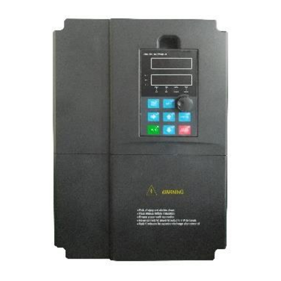
Less than 95% RH, without condensing Vibration Less than 5.9 m/s2 (0.6 g) 2.2 Installation dimension 2.2.1 Solar inverter appearance and installing dimension(mm) Diagram 2-2 Appearance and installation dimension (Plastic housing structure) Appearance and installing dimension ( Unit: mm ) Matching inverter GK330-XXX-SP1/SP2 GK330-XXX-SP3 0.75~2.2kW... -
Page 8: Appearance And Installation Dimension Of External Keypad (Keypad Tray)
Solar Frequency Inverter Users’ Manual 2. Product Information 2.2.2 Appearance and installation dimension of external keypad (keypad tray) Diagram 2-3 Appearance and installation dimension of external keypad (keypad tray) -
Page 9: Installation Of Frequency Inverter
2. The environment temperature shall be -10℃~40℃. If the temperature is over 40℃, but less than 50℃, rather remove the cover of the solar inverter or open the front door of the cabinet to improve heat dissipation. 3. Try to avoid high temperatures and wet environments; humidity should be less than 90% without likelihood of frost deposits. -
Page 10: Sketch And Description Of Main Circuit Terminals
Solar Frequency Inverter Users’ Manual 3. Installation of Solar Inverter 3.3 Main Circuit Terminals 3.3.1 Function and description of Main Circuit Terminals Power range: 0.75kW~22kW Power range: 30kW~400kW Terminal symbol Function description AC power input terminals R, S, T P+, P-... -
Page 11: Control Circuit Terminal Layout
Solar Frequency Inverter Users’ Manual 3. Installation of Solar Inverter Diagram3-2 Control circuit and main circuit wiring 3.4.2 Control Circuit Terminal Layout Diagram3-3 Control circuit terminal sketch diagram 3.4.3 Description of control circuit terminals Type Symbol Name Terminal function description Provide +10V power supply to external unit. -
Page 12: Collection Diagram For Different Motor
Solar Frequency Inverter Users’ Manual 3. Installation of Solar Inverter Type Symbol Name Terminal function description TA2-TC2 Connected to an external keypad Interface External keypad interface AI1/AI2 output selection, Voltage or Current output. AI1/AI2 AI1: voltage output by default. AI2: current output by default. -
Page 13: The Wiring Of Water-Level Automatic Control
Water Pipe C o n t r o l Te r m i n a l Pump Diagram 3-6 Diagram of 3-phase solar inverter connection method (PV Input) 3.5.1 Wiring for automatic water-level control Wiring of water-level float switch The common cable port of the water-level float switch should be connected to the COM terminal and then connected to the DI1 terminal. - Page 14 The water-level switch mounted on the side is the normally open contact to output and its common wire is connected to the terminal COM of inverter. At the same time, the low level-water wire is connected to terminal DI4 and the high water-level wire is connected the terminal DI5.
-
Page 15: Operation And Display
Current unit Voltage unit STOP/ OFF indicates that the solar inverter is in the stop state and ON indicates that the solar inverter is in the running state. FWD/REV It is Forward/Reversal indicator, ON indicates Reverse rotation. Unit / Status... -
Page 16: Function Code Table
FP-00 to 0. The parameter menu under the user-defined parameter mode can be accessed directly without a password. Group “A” includes solar inverter system parameters. Group “F” includes basic function parameters. Group “U” includes monitoring function parameters. - Page 17 Solar Frequency Inverter Users’ Manual 5. Description of Function Codes Default Code Name Description Unit's digit: Binding keypad command to following frequency source. 0: No binding 1: Frequency source by digital setting 2: AI1 Binding command source to F0-27 0000...
- Page 18 Solar Frequency Inverter Users’ Manual 5. Description of Function Codes Default Code Name Description input maximum value 0.00s~10.00s F4-22 AI2 filter time 00.10s F4-35 DI1delay time 0.0s~3600.0s 0.0s 0.0s~3600.0s F4-36 DI2 delay time 0.0s F4-37 DI3 delay time 0.0s~3600.0s 0.0s F9: Fault and Protection parameters 0~20...
- Page 19 Solar Frequency Inverter Users’ Manual 5. Description of Function Codes Default Code Name Description Vmpp voltage manual FE-02 0-1000.0V 500.0V Reference value 0: General 3-phase ac motor FE-03 Motor Selection 1: Single-phase motor with capacitor 2: Single-phase motor without capacitor...
- Page 20 Solar Frequency Inverter Users’ Manual 5. Description of Function Codes Default Code Name Description FE-40 Power curve point 2 0.0kw-999.9kw 1.5kw FE-41 Power curve point 3 0.0kw-999.9kw 2.0kw FE-42 Power curve point 4 0.0kw-999.9kw 2.5kw FE-43 Flow curve point 0 0.0-999.9m^3/h...
-
Page 21: Description Of Function Codes
▲ and ▼ on the operation panel (or using the UP/DOWN function of input terminals). When the solar inverter is powered on again after power failure, the set frequency reverts to the value of F0-08 (record digital setting frequency) 1: Digital setting (record at power failure) The initial value of the set frequency is the value of F0-08(Preset frequency). - Page 22 0.00Hz If the frequency command is lower than the value of this parameter set by F0-14, the solar inverter can stop, r run at the frequency lower limit, or run at zero speed. The result can be determined by F8-14(setting frequency lower than...
- Page 23 If F0-23 is set to 0, the digital setting frequency value restore to the value of (Preset frequency) after the solar inverter stops. The modification by using keys ▲ and ▼ or the terminal UP/DOWN function is cleared to zero.
-
Page 24: F1 Motor Parameter
It is used to set the base frequency to be modified by using keys ▲ and ▼ or the terminal UP/DOWN function. If the running frequency and setting frequency are different, there will be a large difference between the solar inverter's performance during the acceleration/ deceleration process. Unit's digit: Binding keypad command to following frequency source. -
Page 25: F4 Input Terminals
F4 Input Terminals The inverter provides six digital input (DI) terminals (HDI can be used for high-speed pulse input) and two analog input (AI) terminals. The optional extension card provides another six DI terminals (DI7 to DI12) and one AI terminal (AI3). -
Page 26: F9 Faults And Protection Parameters
F9-09 Fault auto reset times 0~20 It is used to set the times of fault auto resets if this function is used. After the value is exceeded, the solar inverter will remain in the fault state. Do action selection during... -
Page 27: Fe Solar Water Pump Control Parameters
F9-14 0 ~ 99 Fault type It is used to record the types of the most recent three faults of the solar inverter. 0 indicates no fault. It displays the frequency when the latest fault occurs. F9-37 Frequency of fault It displays the current when the latest fault occurs. - Page 28 Solar Frequency Inverter Users’ Manual 5. Description of Function Codes 2: Single-phase motor without capacitor 0: General 3-phase ac motor 1: Single-phase motor with capacitor 2: Single-phase motor without capacitor Diagram 5-3 Photovoltaic water pump control schematic FE-04 CVT proportional gain 1 0.0% - 999.9%...
- Page 29 Solar Frequency Inverter Users’ Manual 5. Description of Function Codes 1: AI1 2: AI2 Analog full-water detection FE-32 0 - 100.0% 25.0% Thresholds detection time of full-water FE-33 0 - 30000sec 10sec protection exit time of full-water FE-34 0 - 30000sec...
-
Page 30: Fp User Password Parameters
Solar Frequency Inverter Users’ Manual 5. Description of Function Codes Diagram 5-5 P-Q curve FP User password parameters User password 0 ~ 65535 FP-00 If it is set to any non-zero number, the password protection function is enabled. After a password has been set and taken effect, you must enter the correct password in order to enter the menu. -
Page 31: Fault Diagnosis And Solution
Solar inverter has 35 types of warnings and protection functions. In case of abnormal fault, the protection function will be invoked, the inverter will stop output, and the faulty relay contact of the inverter will start, and the fault code will be displayed on the display panel of the inverter. Before consulting the service department, the user can perform self-check according to the prompts of this chapter, analyze the fault cause and find out t solution. - Page 32 1: The load is too heavy or locked- rotor occurs on the 1: Reduce the load and check the motor and mechanical motor. condition. 2: The solar inverter model is of too small power class. 2: Select a solar inverter of higher power class. Fault Code Err12...
-
Page 33: Appendix I. Modbus Communication Protocol
The solar inverter provides a RS485 communication interface, and adopts MODBUS communication protocol. Users can carry out centralized monitoring via PC/PLC to get operating requirements. And user can set the running command, modify or read the function codes, the working state or fault information of solar inverter by Modbus communication protocol. - Page 34 Here, master is personnel computer (PC), industrial machine or programmable logical controller (PLC), and the slave is inverter. Master not only visits some slave, but also sends the broadcast information to all the slaves. For the single master “Inquiry/Command”, all of slaves will return a signal that is a response; for the broadcast information provided by master, slave needs not feedback a response to master machine.
- Page 35 Communication address:1 to 247(0: broadcast address) 03: Read slave parameters Command code (CMD) 06: Write slave parameters It indicates the external parameter address of solar inverter in hexadecimal Function code address (H) format; There are functional code or non-functional code (such as running state parameter/ running command parameters) type parameters, for details see the address definition.
- Page 36 Some parameters cannot be changed during operation, some parameters regardless of what kind of state the inverter in, the parameters cannot be changed. Change the function code parameters, pay attention to the scope of the parameters, units, and relative instructions.
- Page 37 1020H Auxiliary frequency Y display Note: Communication setting value is the percentage of relative value, 10000 corresponds to 100%, -10000 corresponds to -100.00%. Control command input solar inverter: (write in only) Command word address Command function 0001: Forward running 0002: Reverse running...
- Page 38 Solar Frequency Inverter Users’ Manual BIT0: DO1 output control BIT1: DO2 output control BIT2: Relay 1 output control BIT3: Relay 2 output control BIT4: FMR output control 2001H BIT5: VDO1 BIT6: VDO2 BIT7: VDO3 BIT8: VDO4 BIT9: VDO5 Analog output AO1 control: (write in only)
- Page 39 9: 115200 BPS This parameter is used to set the data transfer rate from host computer and the solar inverter. Please note that baud ratio of the host computer and the inverter should be consistent. Otherwise, communication is impossible. The higher the baud ratio is, the faster the communication is.
- Page 40 Solar Frequency Inverter Users’ Manual Code Parameter Name Setting Range Default Communication 0: 0.01A Fd-06 reading current 1: 0.1A resolution It is used to confirm the unit of current value when the communication reads the output current.
Need help?
Do you have a question about the GK330-D75-SP2 and is the answer not in the manual?
Questions and answers