
Related Manuals for modway Hudson EEI-6860


Summary of Contents for modway Hudson EEI-6860
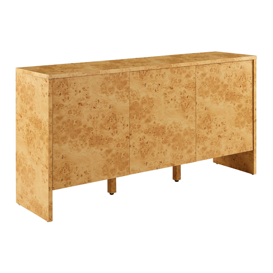
- Page 1 A S S E M B LY I N S T R U C T I O N S EEI-6860 V0.01.01.24 Questions? Contact us! 609.256.9000 • cs@modway.com www.modway.com...
-
Page 2: What You Need
Backply Stopper L Plate Screw M4 x 10 mm Screw M10 x 33.5 mm Wall Bracket Set Missing parts or hardware? Need assistance? Contact us before returning your item. We're here to help! 609.256.9000 • cs@modway.com PAGE 2 OF 11... - Page 3 Cam Bolt Ø7.5 x 32 mm Plastic Dowel M8 x 32 mm Screw M6 x 8 mm Push To Open Bottom Board Cam Bolt Ø7.5 x 32 mm Plastic Dowel M8 x 32 mm Divider Left Board Divider Right Board PAGE 3 OF 11...
- Page 4 Screw M10 x 33.5 mm Screw M10 x 33.5 mm PAGE 4 OF 11...
- Page 5 Cam Lock Ø15 mm Right Board L Plate Screw M4 x 10 mm Left Board PAGE 5 OF 11...
- Page 6 H-Profile Right Board Cam Lock Ø15 mm Cam Cover Ø17 mm Left Board Left Divider PAGE 6 OF 11...
- Page 7 Screw M4 x 19 mm Backply Stopper Screw M3 x 12 mm MUST INSTALLED BACKBOARD AT FLAT SURFACE Full Curve Door Hinge Half Curve Door Hinge Screw M4 x 10 mm PAGE 7 OF 11...
- Page 8 Right Board ADJUST “PUSH TO OPEN” PUSH PUSH PAGE 8 OF 11...
- Page 9 Middle Door ADJUST “PUSH TO OPEN” PUSH PUSH PAGE 9 OF 11...
-
Page 10: Adjustable Feet
Shelf Pin M7 x 16,5 mm ADJUSTABLE FEET ADJUSTED FLOOR FLOOR FLOOR PAGE 10 OF 11... -
Page 11: Connect With Us
Never use harsh chemicals, as they could damage the finish or integrity of the item. Max 7Kgs Max 7Kgs CONNECT WITH US! Max 7Kgs Tag us @modway_furniture #modway for a chance to be featured. PAGE 11 OF 11... -
Page 12: Installation Instructions
4. Lace the end of the restrains strap through the larger hole in each bracket. Ensure the restrains strap with grids surface facing the inner loops. Bring both ends together and slide the flat end through the locking end and draw it through until all slack is removed. 5. Make sure that the strap is securely laced & locked. Customer Service 609.256.9000 | www.modway.com...
Need help?
Do you have a question about the Hudson EEI-6860 and is the answer not in the manual?
Questions and answers