Table of Contents
Advertisement
Quick Links
INSTALLATION | OWNER'S MANUAL
WARNING:
FIRE OR EXPLOSION HAZARD
Failure to follow safety exactly could result in
serious injury, death, or property damage.
•
Do not store or use gasoline or other
flammable vapors and liquids in the vicinity
of this or any other appliance.
-
WHAT TO DO IF YOU SMELL GAS
•
Do not try to light any appliance.
•
Do not touch any electrical switch; do not
use any phone in your building.
•
Leave the building immediately.
•
Immediately call your gas supplier from a
neighbor's phone. Follow the gas supplier's
instructions
•
If you cannot reach your gas supplier, call
the fire department.
-
Installation and service must be performed
by a qualified installer, service agency or the
gas supplier.
CF + D | Custom Fireplace Design Inc.
5230 Harvester Rd #2, Burlington, ON L7L 4X4
T. 1-866-909-3070 t. 905-681-3070. www.customfireplacedesign.com
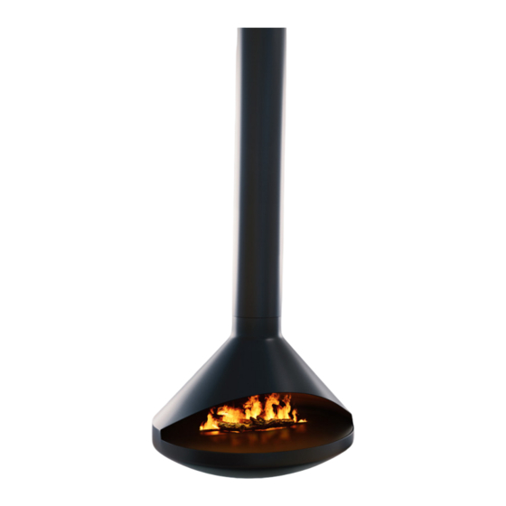
AIDAN Single-Sided | Suspended
Gas Fireplace
MODEL
PM G - 1 2 90 - A I D A N
SERIAL NO.
YY M M D D - VA D O1 X X- XX X X X X
Fireplace has been tested and
certified to meet the standards of:
ANSI Z21.50:19 - CSA 2.22:19
Vented Decorative Gas Appliances
Certified under : ICC-ES PMG-1290
INSTALLER: Leave this manual with the appliance.
CONSUMER: Retain this manual for future reference.
This appliance may be installed in an aftermarket,
permanently located, manufactured home (USA only)
or mobile home, where not prohibited by local codes.
This appliance is only for use with the type of gas
indicated on the rating plate. This appliance is not
convertible for use with other gases.
The installation must conform with local codes or, in
the absence of local codes, to the National Fuel Gas
Code, ANSI 2223.1/NFPA 54, or the Natural Gas and
Propane Installation Code, CSA B149.1.
FOR USE WITH GLASS DOORS CERTIFIED
WITH THE APPLIANCE ONLY
IMPORTANT: Read this owner's manual thoroughly
before trying to assemble, operate, or service this
Fireplace. Improper use of this unit can cause serious
injury or death from burns, fire, explosion, electrical
shock, and carbon monoxide poisoning.
WARNING:
Improper
alteration, service, or maintenance can cause injury or
property damage. Refer to the owner's information
manual provided with this.
installation,
adjustment,
REV. 01
08/01/2020
Advertisement
Chapters
Table of Contents
Troubleshooting

Related Manuals for CF+D VITA AIDAN


Summary of Contents for CF+D VITA AIDAN
- Page 1 INSTALLATION | OWNER'S MANUAL AIDAN Single-Sided | Suspended Gas Fireplace MODEL PM G - 1 2 90 - A I D A N SERIAL NO. YY M M D D - VA D O1 X X- XX X X X X Fireplace has been tested and certified to meet the standards of: ANSI Z21.50:19 - CSA 2.22:19...
- Page 2 FIREPLACE SAFETY INSTRUCTIONS VENTED DECORATIVE GAS APPLIANCE: Young children should be carefully supervised when they NOT A SOURCE OF HEAT; NOT FOR USE are in the same room as the appliance. Toddlers, young WITH SOLID FUEL. children, and others may be susceptible to accidental contact burns.
- Page 3 FIREPLACE SAFETY INSTRUCTIONS Any safety screen, guard, or barrier removed for servicing Only high heat Silicone must be used to seal each an appliance must be replaced prior to operating the connection points and/or area. appliance. Chimney, Venting, Burner area and all other important Clothing or other flammable material should not be areas of the fireplace shall be kept in good condition placed on or near the appliance.
-
Page 4: Table Of Contents
TABLE OF CONTENTS APPENDIX-A 1. General Information......................Page 1 2. Letter From the President....................Page 2 3. Fireplace Component Breakdown..................Page 3 4. Rating Plate..........................Page 4 5. Installation Requirements..................... Page 5 6. Vertical Termination....................... Page 6 » Fireplace Specifications....................Page 7 »... - Page 5 APPENDIX-A REV. 01 08/01/2020...
-
Page 6: General Information
GENERAL INFORMATION KEEP THIS MANUAL HANDY FOR EASY REFERRAL. All NOTES, WARNING, and CAUTION statements will appear in bold font and/or uppercase letters: THEY SHOULD BE STRICTLY OBSERVED. This installation manual is to serve as a guidebook to the installation of your fireplace system. It is not intended to replace skilled trades and/or expertise that may be required to perform installations. - Page 7 A LETTER FROM OUR PRESIDENT Quality Creativity Innovation Our entire team joins me in thanking you for purchasing this AIDAN Single-Sided | Suspended Gas Fireplace, North American designed and manufactured by CF + D | custom fireplace design. We are proud of our quality workmanship, our creativity in designing functional art pieces and our commitment to technical innovation.
-
Page 8: Fireplace Component Breakdown
FIREPLACE COMPONENT BREAKDOWN AIDAN Single-Sided | Suspended Gas Fireplace BURNER SYSTEM Model Manufacturer Listed to/Certified by: PB-16 w/EPK-1 RH Peterson ANSI Z21.60-2012/CSA 2.26-2012 BURNER CHARACTERISTICS Description Natural Gas Liquid Propane Btu’s 45000 40000 Min. Input pressure supply 7” of water column 11”... -
Page 9: Rating Plate
RATING PLATE 5230 Harvester Rd., Unit B2 Burlington, ON L7L 4X4 Ph: 905-681-3070 Toll: 1-866-909-3070 Fireplace has been tested and proved to comply with ANSI Z21.50-2019 • CSA 2.22-2019 Vented Decorative Gas Appliances. Certified under ICC-ES PMG-1290 Made in Canada MODEL: PMG-1290-AIDAN SERIAL: XXXX VENTED GAS FIREPLACE;... -
Page 10: Installation Requirements
INSTALLATION REQUIREMENTS Electrical & Connection A) Installation Requirements Requirements • Prepare the installation location for the fireplace. NOTE: The Enervex Intelli Draft Power Vent • KEEP PACKAGING AND FOAM on the unit System electrical installation must be completed until installation is complete. Once the installation is BEFORE installing your fireplace! complete, remove the rest of the packaging material. -
Page 11: Vertical Termination
VERTICAL TERMINATION Page 6 REV. 01 08/01/2020... -
Page 12: Fireplace Specifications
FIREPLACE SPECIFICATIONS POWER EXHAUST FAN W/ AUTOMATIC WEATHERPROOF DAMPER JUNCTION BOX PRESSURE B-VENT CHIMNEY SENSOR SYSTEM W/ BALANCING DAMPER & DRAFT STORM HOOD CONNECTOR COLLAR FLASHING W/ ANCHOR ROOF SUPPORT PLATE & COLD AIR STOP ANCHOR BODY ELECTRICAL & GAS LINE OPENING(4 PLACES) TRIM COLLAR... - Page 13 FIREPLACE SPECIFICATIONS POWER EXHAUST FAN W/ WEATHERPROOF JUNCTION BOX AUTOMATIC B-VENT CHIMNEY DAMPER SYSTEM W/ BALANCING DAMPER PRESSURE STORM COLLAR SENSOR 24" MIN. ABOVE ROOF EXIT FLASHING W/ " SQ. ROOF SUPPORT ANCHOR ANCHOR PLATE & COLD AIR STOP PLATE TOP OF ROOF ELECTRICAL &...
-
Page 14: Anchor Options Diagram
ANCHOR OPTIONS DIAGRAM REV. 01 08/01/2020 Page 9... -
Page 15: Clearance To Combustibles
CLEARANCE TO COMBUSTIBLES NOTE: WHEN POSITIONING THE FIREPLACE, • A MINIMUM 12” DISTANCE BETWEEN A COMBUSTIBLE WALL AND FIREPLACE BODY IS REQUIRED. • 1” WHERE THE ANCHOR OR FLUE CROSSES THE CEILING & ROOF. • 12” FROM FLOOR TO THE BOTTOM OF THE FIREPLACE. •... -
Page 16: Enervex Electrical Diagram
ENERVEX ELECTRICAL DIAGRAM REV. 01 08/01/2020 Page 11... -
Page 17: Horizontal Termination
HORIZONTAL TERMINATION REV. 01 08/01/2020 Page 12... -
Page 18: Fireplace Specifications
FIREPLACE SPECIFICATIONS REV. 01 08/01/2020 Page 13... - Page 19 FIREPLACE SPECIFICATIONS B-VENT CHIMNEY PRESSURE POWER EXHAUST WALL BAND SENSOR SYSTEM W/ FAN W/ SUB FLOOR/ROOF BALANCING DAMPER WEATHERPROOF JUNCTION BOX THREADED RODS TO SUPPORT ANCHOR WALL THIMBLE (BY OTHERS) ELECTRICAL AND ANCHOR " SQ. ANCHOR GAS LINE OPENING AUTOMATIC PLATE PLATE (4 PLACES)
-
Page 20: Anchor Options Diagram
ANCHOR OPTIONS DIAGRAM REV. 01 08/01/2020 Page 15... -
Page 21: Clearance To Combustibles
CLEARANCE TO COMBUSTIBLES NOTE: WHEN POSITIONING THE FIREPLACE A MINIMUM OF • 12” DISTANCE BETWEEN A COMBUSTIBLE WALL AND FIREPLACE BODY IS REQUIRED, • 12” FROM BOTTOM OF THE FIREPLACE TO THE FLOOR • 1” WHERE THE ANCHOR OR FLUE CROSSES THE CEILING/ROOF. •... -
Page 22: Enervex Electrical Diagram
ENERVEX ELECTRICAL DIAGRAM REV. 01 08/01/2020 Page 17... -
Page 23: Fireplace Installation
FIREPLACE INSTALLATION Install the Anchor Assembly The anchor is the first piece to be installed, ANCHOR MOUNTING HOLES (4 NOS.) it will hold the weight of the flue pipe, and the fireplace body while suspending the unit from the ELECTRICAL & GAS ANCHOR LINE OPENING ceiling or roof. - Page 24 FIREPLACE INSTALLATION NOTE: Install the Trim Collar Fit the trim collar around the Anchor pipe IF THE CEILING HEIGHT IN YOUR and slide it upwards to meet the finished ceiling. Affix APPLICATION IS MORE THAN THE CF + D’s STANDARD the trim collar to the finished ceiling either by using CEILING HEIGHT APPLICATION, YOU MAY HAVE BEEN 4 screws (not provided), or other means of attachment...
- Page 25 FIREPLACE INSTALLATION Install the Flue Pipe Remove the anchor service door. Install the flue pipe into the anchor body, ensuring that the gas line conduit inside the flue pipe lines up with the access opening on the anchor body. The flue pipe have already been cut to the proper installation length.
- Page 26 FIREPLACE INSTALLATION Install the Fireplace Body There are alignment marks on the flue and the fireplace body right at the seam on the rear. Align these marks when installing the fireplace body to the flue at what would be considered the rear of the application. The Flue Pipe contains the Gas/Electrical Conduit for Gas Fireplace.
- Page 27 ELECTRICAL & GAS LINE OPENING(4 PLACES) FIREPLACE INSTALLATION SERVICE DOOR NOTE: This fireplace is equipped with an (TO ACCESS GAS AND Enervex Power Vent System, there will be an ELECTRICAL additional connector to run the Enervex wires through the conduit with the gas line. CONNECTIONS) THE CONNECTION DETAIL: Since this connection must be air-tight, the gas line from the...
- Page 28 FIREPLACE INSTALLATION Connecting the conduits for Install the multiple flue multiple flue sections. (If applicable) sections. (If applicable) Note: This step is only required if you have multiple flue Note: This step is only required if you have multiple sections based on your ceiling height. flue sections based on your ceiling height.
- Page 29 FIREPLACE INSTALLATION Install the Decorative Before installing the decorative chimney, install all the B-Vent components on the chimney venting Chimney (OPTIONAL) installation collar. Please refer to Appendix-B, Chimney (VERTICAL TERMINATION) Venting Installation for detailed installation steps. DO NOT INSTALL THE ENERVEX COMPONENTS If you have chosen to have the decorative NOW.
- Page 30 FIREPLACE INSTALLATION Install the Decorative Chimney For connection with ENERVEX power fan please refer Appendix-B - Enervex intelli draft system (OPTIONAL) (HORIZONTAL instructions. TERMINATION) NOTE : ALL THE CONNECTIONS, SEAMS AND JOINTS OUTSIDE THE WALL SHALL If you have chosen to have the decorative BE SEALED WITH HIGH HEAT SILICONE chimney cover, please follow the instructions below to TO PREVENT WATER ENTERING FROM...
- Page 31 APPENDIX-B REV. 01 08/01/2020 Page 26...
-
Page 32: Burner Installation | Operation
BURNER INSTALLATION | OPERATION This fireplace is pre-assembled with the burner Check for gas leaks at the burner, field made installed and factory set. joints/gas shut off valve, and pilot too. If a leak persist, turn off the gas supply and contact the local gas company Follow the instructions below for completing or dealer. -
Page 33: Lighting Instructions
LIGHTING INSTRUCTIONS Safety Information Operating Instructions 1. STOP! Read the safety information above. This appliance is equipped with an ignition device which automatically lights the pilot. Do not try to light 2. Turn off any electrical components used with the the pilot by hand. -
Page 34: Chimney | Venting Installation & Operation
CHIMNEY | VENTING INSTALLATION & OPERATION Steps For Typical Installation A major cause of vent related fires is failure to maintain required clearances (air spaces) 1. Building Code requires the fireplace to be located to combustible materials. It is of the utmost as close to the vent as possible. - Page 35 CHIMNEY | VENTING INSTALLATION & OPERATION For 10” through 16” diameter pipe, use a minimum of 10. Where the Pipe Sections pass through the roof, a ” sheet metal screws per joint, and a minimum of hole must be cut to provide a minimum clearance (air space) of 1 inch between the Pipe and construction ”...
-
Page 36: Enervex Intelli Draft System
CHIMNEY | VENTING INSTALLATION & OPERATION Adjustable Elbows ENERVEX INTELLI DRAFT SYSTEM (OVERVIEW): 1. This section furnishes supplemental information concerning Adjustable Elbows, both 90° and 45°/60°. The Intelli Draft connects a draft and safety controller, the ADC100 and its pressure sensor, to an 2. - Page 37 CLEANING AND MAINTENANCE Flame Description WARNING: Observe the flames. the flames should be blue Turn off gas before servicing fireplace. It is recommended at the base and a combination of blue/yellow at the that a qualified service technician perform these check- body and tips.
- Page 38 For ordering replacement parts, please contact CF + D | custom fireplace design. CLOSING If there are any questions regarding any aspect of the work to be undertaken, please contact your Technical Representative at CF+D for assistance. We thank you for your support and your business! Page 33 REV.
- Page 39 WARRANTY Quality Creativity Innovation All Fireplace models are guaranteed against any defect in design, construction, or manufacture, and guaranteed to function properly for five (5) years from date of receipt of goods. The electrical and electronic components within the fireplace are warranted against any defect in design, construction, or manufacture, and guaranteed to function properly for one (1) year from date of commissioning.
- Page 40 5230 Harvester Rd. Unit #2 Burlington, Ontario Canada L7L 4X4 T. 1-866-909-3070 t. 905-681-3070 www.customfireplacedesign.com REV. 01 08/01/2020...
- Page 41 ENERVEX ADC100 DRAFT CONTROL 3916067 05.17 Installation & Operating Manual READ AND SAVE THESE INSTRUCTIONS! ENERVEX Inc. P: 770.587.3238 1685 Bluegrass Lakes F: 770.587.4731 Parkway T: 800.255.2923 Alpharetta, GA 30004 info@enervex.com www.enervex.com...
- Page 42 3916067 05.17 The ADC100 Fan Control is ETL Listed in the U.S. and Canada: under UL 508 Standard for Industrial Control Equipment (17th Ed.) and CSA C22.2 No. 14-05- Standard for Industrial Control Equipment. IMPORTANT: READ THESE INSTRUCTIONS CAREFULLY PRIOR TO INSTALLATION. •...
- Page 43 3916067 05.17 Content 1. PRODUCT INFORMATION 1.1 Function ..............4 1.2 Shipping ..............4 1.3 Warranty ..............4 2. SPECIFICATIONS AND DIMENSIONS 2.1 Dimensions and Capacities ........5 3. MECHANICAL INSTALLATION 3.1 Location..............6 3.2 Mounting the Control Unit ........6 3.3 Connection of the Proven Draft Switch ....
-
Page 44: Product Information
3916067 05.17 1. PRODUCT INFORMATION 1.2 SHIPPING 1.1 FUNCTION ADC100 includes the control unit, PDS1, stack probe and The ENERVEX ADC100 Draft Control is a fan speed and silicone tubing. appliance control used to control draft for a gas appliance such as a fireplace, stove or furnace. -
Page 45: Dimensions And Capacities
3916067 05.17 2. SPECIFICATIONS 2.1 DIMENSIONS AND CAPACITIES ADC100 Control Power supply 1x120VAC Amperage ADC100 Operating temperature °F/°C -4 to 122 / -20 to 50 Control signal max. 10 Control relay Max. 120 VAC / 8A Output 10-120 0-10 Post Purge Time 0-3 Minutes Alarm Delay Time 15 Seconds... -
Page 46: Mechanical Installation
3916067 05.17 3. MECHANICAL INSTALLATION 3.1 LOCATION The ADC100 Control Unit must be installed indoors. As shown in Fig. 1, the control will be wired directly to a 120/1/60 VAC power supply. The control will also be connected to the fan, appliance and damper (if used). For detailed wiring information, see Chapter 4. -
Page 47: Installation Of The Chimney Probe
3916067 05.17 3.4 INSTALLATION OF THE CHIMNEY PROBE The probe must be installed between the appliance and the exhaust fan. If a damper is used in the system, the probe should be installed between the appliance and damper. Locate the probe at least a distance three (3) vent diameters away from any elbow, tee or damper. -
Page 48: Electrical Installation
3916067 05.17 4. ELECTRICAL INSTALLATION 4.1 GENERAL DANGER Turn off electrical power before servicing. Contact with live electric components can cause shock or death. ADC100 is designed for 1x120VAC power supply only. The designations for each terminal on the control board are shown below. -
Page 49: Connection Diagram
3916067 05.17 4.2 CONNECTION DIAGRAM The connection diagram shown in Fig. 7 below shows typical connections for a single phase fan. If a 3-phase fan is used, a VFD must be connected between the fan and control. ADC 100 ENERVEX To Fireplace Fig. -
Page 50: Wiring Of A Gas Fireplace
3916067 05.17 4.3 WIRING OF A GAS FIREPLACE To interlock the ADC100 with a gas fireplace as shown in Fig. 8, connect the Auxiliary In terminals 9 and 10 on the control board to a wall switch. Either by using line voltage or use board voltage from terminals 7 and 8 as depicted in figure 8. -
Page 51: Wiring Of A Gas Fireplace With A Damper
3916067 05.17 4.4 WIRING OF A GAS FIREPLACE WITH A DAMPER To interlock the ADC100 with a gas fireplace as shown in Fig. 9, connect the Auxiliary In terminals 9 and 10 on the control board to a wall switch. Either by using line voltage or use board voltage from terminals 7 and 8 as depicted in Fig. -
Page 52: Wiring Of 3-Phase Fan
3916067 05.17 4.5 WIRING A 3-PHASE FAN Connect a 3-phase fan to the control system via a variable frequency drive (VFD). The VFD receives external 3-phase power (208-230 or 400-480 VAC). A 0-10 VDC signal from the ADC100 is converted to a 0-60 Hz signal from the VFD to modulate the fan speed. -
Page 53: Startup And Configuration
3916067 05.17 5. STARTUP AND CONFIGURATION 5.1 GENERAL Dip switches are located on the control board to allow the user to specify certain functions of the ADC100. Verify settings using the table below. DEFAULT DIP SWITCH NAME POSITION Manual reset at Automatic reset at power MANUAL power failure or... -
Page 54: Sequence Of Operation
3916067 05.17 5.2 SEQUENCE OF OPERATION The sequence of operation flow chart is shown in Figure 11 below. Maintain Flashing State Idle State De- Energize for 30 seconds All for Retry Aux In Enabled Taking longer than One Flash Open Damper 90 seconds Alarm Damper Open Proof... -
Page 55: Operating Pressure
3916067 05.17 5.3 OPERATING PRESSURE The operating pressure of the ADC100 Control is determined by the PDS switch. The PDS-1 used with the ADC100 has a pressure setting of 0.05" W.C. +/- 0.03" W.C. As long as the pressure is within this range, the fireplace and/or appliance will continue to operate. -
Page 56: Maintenance And Troubleshooting
6. MAINTENANCE AND TROUBLESHOOTING Observation Problem Solution Heating appliance/fireplace cycle Potentiometer setting is too low Turn potentiometer clockwise to increase fan speed on and off Fan speed control is set too low Increase potentiometer setting Fan is ‘hunting’ (increasing speed and then decreasing speed constantly) Draft in chimney fluctuates... - Page 57 ENERVEX ADM & ADF AUTOMATED DAMPER 3903005 08.18 Installation & Operating Manual READ AND SAVE THESE INSTRUCTIONS! UL File E467733 ENERVEX Inc. P: 770.587.3238 1685 Bluegrass Lakes F: 770.587.4731 Parkway T: 800.255.2923 Alpharetta, GA 30004 info@enervex.com www.enervex.com...
- Page 58 3903005 08.18 UL File E467733 This symbol shows that the ENERVEX ADM/ADF Automatic Dampers are listed in the US and certified for Canada under Underwriters Laboratories Inc. file no. E467733. IMPORTANT: READ THESE INSTRUCTIONS CAREFULLY PRIOR TO INSTALLATION. • EXAMINE ALL COMPONENTS FOR POSSIBLE SHIPPING DAMAGE PRIOR TO INSTALLATION. •...
- Page 59 3903005 08.18 Content 1. PRODUCT INFORMATION 1.1 Function ............3 1.2 Shipping ............3 1.3 Warranty ............3 2. SPECIFICATIONS AND DIMENSIONS 2.1 Dimensions and Capacities .......4 3. MECHANICAL INSTALLATION 3.1 General .............5 4. ELECTRICAL INSTALLATION 4.1 Wiring ...............6 5. MAINTENANCE 5.1 General .............7 1.
- Page 60 3903005 08.18 2. SPECIFICATIONS AND DIMENSIONS 2.1 DIMENSIONS AND CAPACITIES Stack ID Dia. A Dim. B Dim. C Dim. D Model (in) in / mm in / mm in / mm in / mm ADM 6 5.85 / 146 8.0 / 203 7.85 / 199 10.85 / 276 ADM 8...
- Page 61 3903005 08.18 3. MECHANICAL INSTALLATION 3.1 GENERAL The ADM has male-male slip connections. Install the ADM in the vent system at least one vent diameter (B) plus one foot Damper above an appliance outlet and at least three vent diameters away from any tee or elbow.
- Page 62 3903005 08.18 4. ELECTRICAL INSTALLATION 4.1 WIRING DANGER 120 VAC Turn off electrical power before servicing. Contact with live electric components can cause 1 Neutral N L1 shock or death. H L2 2 Hot Éteignez l’alimentation électrique avant de procéder à l’entretien.
- Page 63 3903005 08.18 5. MAINTENANCE 5.1 GENERAL Annual maintenance is recommended. During the maintenance check, verify the damper blade is in the correct position (the indicator on the damper rod will show the position of the damper blade). Check that the damper rod is firmly secured by the actuator and tighten fasteners if necessary.
- Page 64 ENERVEX Inc. P: 770.587.3238 1685 Bluegrass Lakes F: 770.587.4731 Parkway T: 800.255.2923 Alpharetta, GA 30004 info@enervex.com www.enervex.com...
- Page 65 ENERVEX RS CHIMNEY FAN FOR GAS & OIL APPLICATIONS 3000270 08.17 Installation & Operating Manual READ AND SAVE THESE INSTRUCTIONS! ETL514733 ENERVEX Inc. P: 770.587.3238 1685 Bluegrass Lakes F: 770.587.4731 Parkway T: 800.255.2923 Alpharetta, GA 30004 info@enervex.com www.enervex.com...
- Page 66 3000270 08.17 ETL514733 This symbol shows that ENERVEX RS Chimney Fans for solid fuel applications are listed under ETL File no. 514733. Symbol Legend The following terms are used throughout this manual to bring TO REDUCE THE RISK OF FIRE, attention to the presence of potential hazards, or to important ELECTRICAL SHOCK OR INJURY TO information concerning the product.
- Page 67 3000270 08.17 Content 1. GENERAL INFORMATION 1.1 Function ....................4 1.2 Shipping ....................4 1.3 Warranty ....................4 2. SPECIFICATIONS AND DIMENSIONS 2.1 Dimensions and Capacities ...............5 2.2 Planning Ahead .................6 3. MECHANICAL INSTALLATION 3.1 Transport Safety Device ..............7 3.2 Single Fan on Steel Chimney .............7 3.3 Single Fan on Brick Chimney .............8 3.4 Multiple Fans on Steel Chimney ............9 3.5 Multiple Fans on Brick Chimney - Oversized Flue .......9...
-
Page 68: General Information
3000270 08.17 1. GENERAL INFORMATION 1.1 FUNCTION The RS Chimney Fan is a chimney top mounted ventilator that is designed to provide large flue gas volume capacities. It is designed and intended for use with residential gas or oil fired central space heating systems, for volume water heating or for combination space heating/volume water heating. -
Page 69: Dimensions And Capacities
3000270 08.17 2. SPECIFICATIONS 2.1 DIMENSIONS & CAPACITIES Model RS 009 RS 012 RS 014 RS 016 Discharge Horizontal Fan Type Axial Vane Motor Type Totally enclosed, Variable speed, Class H Voltage 1x120V @ 60 Hz Amperage Amps 1600 @0.0 Ps 1400 1950 Motor Output... -
Page 70: Planning Ahead
3000270 08.17 2.2 PLANNING AHEAD Observe proper combustion air requirements. System type Direct connect oil or gas appliances (no draft hood) normally Provide a firm support system for the chimney fan. do not require any mechanical draft adjustment. However, Determine the type of system involved. if there are long horizontal breechings and far between Observe proper safety measures are taken the appliances, it is a good idea to install mechanical vent... -
Page 71: Mechanical Installation
3000270 08.17 3. MECHANICAL INSTALLATION 3.1 TRANSPORT SAFETY DEVICE If a transport safety device is present, remove it from the vane and make sure that the vane can revolve without hindrance. RS 14/16: Before mounting, the transport safety device on the hinges must be removed. -
Page 72: Single Fan On Brick Chimney
3000270 08.17 3.3 SINGLE FAN ON BRICK CHIMNEY Step 1: Prepare fan location The installation procedure is the same whether the flue is round or square. If a clay tile flue liner is installed, it might stick up a few inches. Cut it back so it is flush with or no more than 1/2 inch above the chimney crown. -
Page 73: Multiple Fans On Steel Chimney
3000270 08.17 3.4 MULTIPLE FANS ON STEEL CHIMNEY If two or more chimney fans are required to create sufficient draft, installation procedures are the same as for single fan installation on a steel chimney. The only difference is that the fans are sitting next to each other on the top of the chimney. -
Page 74: Wall Mounting Of Chimney Fan
3000270 08.17 3.7 WALL MOUNTING OF CHIMNEY FAN When mounting the chimney fan on a wall, the installation instructions for installation on a steel chimney should be Bolt followed. Use of the adapter SCA can make the installation easier, but is not a requirement. To ease installation, detach the fan base by removing the bolts holding the hinges together. - Page 75 3000270 08.17 The combustion air inlet and flue gas outlet of a direct vent appliance or the flue gas outlet of an appliance other than a direct vent appliance shall terminate at least 1 ft (0.3 m) from the soffit of the roof of the structure and at least 3 ft (0.9 m) from an inside corner of an L-shaped structure.
-
Page 76: Electrical Installation
3000270 08.17 4. ELECTRICAL INSTALLATION 4.1 GENERAL DANGER Turn off electrical power before servicing. Contact with live components can cause shock or death. All electrical wiring must be in compliance with the local codes or in their absence, with the National Electric Code, NFPA 70 —... -
Page 77: Wiring Diagram For Single Fan With Fsc
3000270 08.17 4.3 WIRING DIAGRAM FOR TWO FANS WITH FAN SPEED CONTROL The diagrams at right show the wiring of two chimney fans PROVEN DRAFT SWITCH and how they are connected to the fan speed control. 24 VAC MOTOR MOTOR 24V GAS VALVE 120/1/60 WEATHERPROOF... -
Page 78: Startup And Configuration
3000270 08.17 5. STARTUP AND CONFIGURATION 5.1 SYSTEM TESTING Before any adjustments are made to the system, follow these procedures: 1. Turn the chimney fan ON and make sure that it is operating. Increase and decrease the speed of the fan by adjusting the fan speed control to make sure it is operating properly. -
Page 79: Maintenance And Troubleshooting
3000270 08.17 6. MAINTENANCE AND TROUBLESHOOTING 6.1 PRIOR TO CLEANING Remove butterfly nut or screw from each hinge prior to cleaning. Remove Butterfly Nut or Screw from each Hinge 6.2 CARE AND CLEANING The Chimney Fan System is designed for prolonged use. The fan should be inspected at least one a year when the chimney is inspected. -
Page 80: Troubleshooting
6.4 TROUBLESHOOTING Observation Problem Solution – The circuit breaker may be off – Check the circuit breaker There is no power going to the fan – Fan speed control is off – Turn fan speed control on – Bad electrical connections –...
Need help?
Do you have a question about the VITA AIDAN and is the answer not in the manual?
Questions and answers