Table of Contents
Advertisement
Quick Links
VITA | Fireplaces
North American Designed & Manufactured by CF + D | custom fireplace design
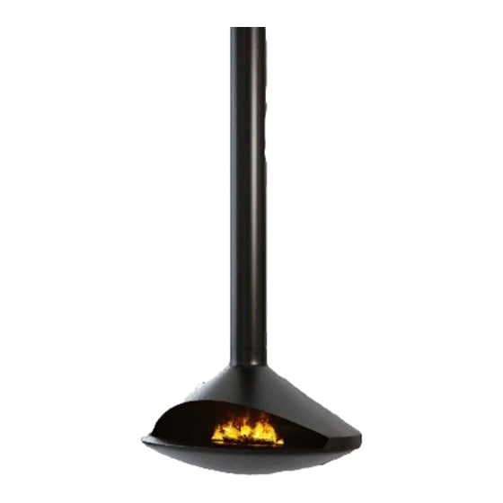
GIOIA | See-Thru
Suspended Fireplace with Vapor-Fire Burner
INSTALLATION | OWNER'S MANUAL
Serial #
Read full manual before installation and keep all instruction for future use
4/2/19
CF + D | custom fireplace design
www.customfireplacedesign.com
Advertisement
Table of Contents

Related Manuals for CF+D VITA GIOIA See-Thru


Summary of Contents for CF+D VITA GIOIA See-Thru
- Page 1 VITA | Fireplaces North American Designed & Manufactured by CF + D | custom fireplace design GIOIA | See-Thru Suspended Fireplace with Vapor-Fire Burner INSTALLATION | OWNER'S MANUAL Serial # Read full manual before installation and keep all instruction for future use 4/2/19 CF + D | custom fireplace design www.customfireplacedesign.com...
-
Page 2: Table Of Contents
Table of Contents APPENDIX A - VITA | Fireplaces Installation Important Instructions........................Page A General Information........................Page B Fireplace Specifications.......................Page C Installation Requirements......................Page D a) Installation Requirements b) Required Tools c) Description Anchor Plate Installation......................Page E Anchor Plate Options Diagram....................Page F Flue Pipe Installation........................Page G Flue Pipe Extension Instructions....................Page H Trim Collar Installation.......................Page H Fireplace Body Installation......................Page H... -
Page 3: Appendix A - Vita | Fireplaces Installation
VITA | Fireplaces Installation Quality Creativity Innovation A Letter from Our President: Our entire team joins me in thanking you for purchasing the GIOIA See-Thru Suspended fireplace, part of our exclusive line of VITA | Fireplaces featuring Vapor-Fire burner technology, North American designed and manufactured by CF + D | custom fireplace design. -
Page 4: Important Instructions
APPENDIX A - Important Instructions IMPORTANT: Read all instructions before installation. Vapor-Fire Burner: 1. Not for use outdoors. 2. DO NOT insert or allow foreign objects to This equipment has been tested and found to enter any ventilation or exhaust opening as this may comply with the limits for Class B digital device, cause electric shock. -
Page 5: General Information
General Information KEEP THIS MANUAL HANDY FOR EASY REFERRAL. All WARNING and CAUTION SHOULD BE STRICTLY OBSERVED. Please read this entire manual before you Some of the components supplied cannot install and use your VITA | Fireplaces Vapor-Fire be installed by a single person nor should they be Feature. -
Page 6: Fireplace Specifications
Fireplace Specifications GIOIA | See-Thru Sample Layout 24" " TYP. OPTIONAL PROVISION FOR ELECTRICAL AND WATER LINE IN FROM TOP 24" ANCHOR PLATE " TYP. ELECTRICAL & WATER LINE " TYP. OPENING ANCHOR PLATE (TOP OR SIDE) ANCHOR 24" SQ. x 0.25" THK. BODY SERVICE DOOR... -
Page 7: Installation Requirements
Installation Requirements INSTALLATION | OWNER'S MANUAL GIOIA See-Thru Suspended Fireplace with Vapor-Fire Burner A) Installation Requirements B) Required tools • Prepare ceiling for the installation of the anchor • Drill plate (see Anchor Plate Options Page F). • M8 Allen key •... -
Page 8: Anchor Plate Installation
Anchor Plate Installation Install the Anchor Plate The first step is to install the anchor plate. Place the anchor in the desired location and ½ The anchor plate will hold the weight of the mount it to the ceiling using ”... -
Page 9: Anchor Plate Options Diagram
Anchor Plate Options Diagram CUSTOM ANCHOR OPTIONS AVAILABLE FLOOR/ROOF 24" SQ. CONCRETE STRUCTURE ABOVE ANCHOR PLATE THREADED ROD FOR 24" SQ. POWER SUPPLY SUSPENDING ANCHOR PLATE ANCHOR PLATE (ELECTR I CAL LINE IN) FROM CONCRETE STRUCTURE JOIST CONTINUOUS WATER POWER SUPPLY SUPPLY (OPTIONAL) CEILING CEILING... -
Page 10: Flue Pipe Installation
Flue Pipe Installation Install the Flue Pipe To Install the flue pipe, raise the pipe up To ensure that the flue pipe is hanging plumb 5/32 to meet the anchor plate that has now been (straight) and level, use a Allen key to tighten positioned. -
Page 11: Fireplace Body Installation
Flue Pipe Extension | Fireplace Body Installation Install the Flue Pipe Extension Install the Trim Collar to Meet Ceiling Requirement Fit the trim collar (See Page C) around ½ " round rod is welded into the bottom the flue pipe and slide it upwards to meet the of the flue extension (See Figure 4 Below). -
Page 12: Electrical Installation
Electrical | Plumbed-In Option Instructions Electrical Installation There are two lifting tabs for ease of use (see diagram below). NOTE: All electrical to be completed first. Do not turn on electrical until plumbing has been completed. ¼ The electrical and ”... -
Page 13: Initial Fill Instructions
Vapor-Fire Burner | Initial Fill Instructions Vapor-Fire Burner Remove top cover assembly on the burner by depressing side tabs gently (images 1 and 2). Remove media tray to access the burners (See Page I). The Vapor-Fire burner is factory set and ready for the initial fill. Confirm that all electrical and plumbing have been completed before proceeding to the next step. - Page 14 Initial Fill (continued) | Manual Fill Instructions Instructions for Manual Fill Option 2: Fill the reservoir using the Initial fill bottle Containers If you have chosen the plumbed-in • Remove the media tray (top tray for rocks, logs option, remove the plumbing fill cap assembly etc.) to access the burners.
- Page 15 Warranty Quality Creativity Innovation Warranty All CF + D and VITA | Fireplaces models are guaranteed against any defect in design, construction, or manufacture, and guaranteed to function properly for five (5) years from date of receipt of goods. The electrical and electronic components within the fireplace are warranted against any defect in design, construction, or manufacture, and guaranteed to function properly for one (1) year from date of commissioning.
- Page 16 APPENDIX B Vapor-Fire Service Manual Vapor-Fire CF + D | custom fireplace design Service Manual For Dimplex Model(s) CDFI1000-PRO 6909660300 CDFI500-PRO 6909660400 IMPORTANT SAFETY INFORMATION: Always read this manual first before attempting to service this cassette. For your safety, always comply with all warnings and safety instructions contained in this manual to prevent personal injury or property damage.
- Page 17 TABLE OF CONTENTS Operation............................3 Maintenance..........................4 Exploded Parts Diagram......................5 Replacement Parts List......................5 Wiring Diagram...........................6 Switch Board Replacement......................7 Terminal Block Replacement......................7 Fan Assembly Replacement.......................8 Fused Wire Harness Replacement.....................8 Main Control Board Replacement....................8 Power Supply Replacement.......................9 LED Light Assembly Replacement...................10 Heating Element Replacement....................10 Level Sensor Assembly Replacement..................11 Solenoid Valve Replacement....................12 Troubleshooting Guide......................13...
- Page 18 Page 3 www.customfireplacedesign.com...
- Page 19 Page 4 www.customfireplacedesign.com...
- Page 20 Page 5 www.customfireplacedesign.com...
- Page 21 Page 6 www.customfireplacedesign.com...
- Page 22 Page 7 www.customfireplacedesign.com...
- Page 23 Page 8 www.customfireplacedesign.com...
- Page 24 Page 9 www.customfireplacedesign.com...
- Page 25 Page 10 www.customfireplacedesign.com...
- Page 26 Page 11 www.customfireplacedesign.com...
- Page 27 Page 12 www.customfireplacedesign.com...
- Page 28 Page 13 www.customfireplacedesign.com...
- Page 29 Page 14 www.customfireplacedesign.com...
- Page 30 Page 15 www.customfireplacedesign.com...
- Page 31 CF + D | custom fireplace design 5230 Harvester Rd. Unit #2 Burlington, Ontario Canada L7L 4X4 t. 1-866-909-3070 t. 905-681-3070 www.customfireplacedesign.com...
Need help?
Do you have a question about the VITA GIOIA See-Thru and is the answer not in the manual?
Questions and answers