Table of Contents
Advertisement
Quick Links
Advertisement
Chapters
Table of Contents

Related Manuals for Barco UniSee

Summary of Contents for Barco UniSee
- Page 1 UniSee and LCD Service Manual ENABLING BRIGHT OUTCOMES...
- Page 2 Barco NV, Control Rooms President Kennedypark 35, 8500 Kortrijk, Belgium www.barco.com/en/support www.barco.com Registered office: Barco NV President Kennedypark 35, 8500 Kortrijk, Belgium www.barco.com/en/support www.barco.com...
- Page 3 Copyright© 2021 by Barco All rights reserved. No part of this document may be copied, reproduced or translated. It shall not otherwise be recorded, transmitted or stored in a retrieval system without the prior written consent of Barco Warranty Statement Please refer to http://www.barco.com/en/aboutbarco/Warranty%20policy...
- Page 5 System overview Introduction ............................6 UniSee View ..........................6 UniSee Mount ..........................9 R5914306 /00 UniSee and LCD...
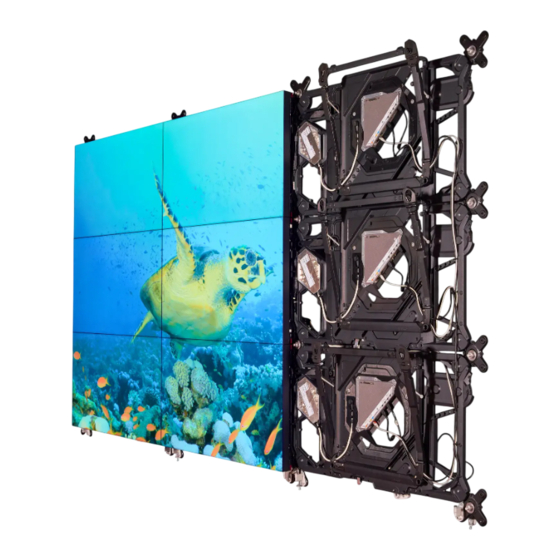
- Page 6 UniSee View is a modular designed professional display available as standard and high brightness version. The LCM is completed by a power supply solution (redundancy option) and an input board solution. The input boards and power supplies of the Barco UniSee system have been designed to be extremely reliable, and easily upgradable.
- Page 7 Each of these inputs has a 4k loop-through connection to the DP1.2 output. Loop-through connection is established as soon as the input is the active input. The max. length of the loop equals 16 for signals without HDCP protection and a resolution of 1920x1080@60Hz. R5914306 /00 UniSee and LCD...
- Page 8 DP 1.2 Support of repeater functionality. Need to be HDCP 1.3: max. 1+7 configured on the display web app. On last HDCP 2.2: max. 1+4 display in the loop, HDCP repeater functionality needs to be disabled R5914306 /00 UniSee and LCD...
- Page 9 It is only the Barco UniSee Mount that unleashes all sophisticated features of the UniSee View displays The UniSee Mount is a sophisticated mechanical innovation that uses the power of gravity to keep the panels perfectly in place, ensuring the precise alignment of the panels. The corners of the LCM ensure that the panels’...
- Page 10 (AC or DC) Position of the input board Installation of the LCM to UniSee Mount is just opening the moving frame and hanging in the LCM. WARNING: The Barco UniSee Mount uses springs to compensate gravity of the LCMs: Actually an LCM will only feel 1/10 of the weight of the LCM on top of it.
-
Page 11: Table Of Contents
Service and maintencance Required Tools ..........................12 Important warnings ........................12 De-mounting of an LCM ........................13 Swap and replace of the physical display..................13 Replacement of the power supply and the input board module ............20 Cleaning ............................41 R5914306 /00 UniSee and LCD... -
Page 12: Required Tools
Mechanical stress Please be careful not to apply strong mechanical stress (shock, drop) to the LCM module. Such stress may cause break of screen glass or may be the cause for failure Pressure to screen surface R5914306 /00 UniSee and LCD... -
Page 13: Mounting Of An Lcm
Insert the tool into the service release drive on the bottom of the MOST RIGHT column (column n) (position service). Tip: The service tool KEY THAN HEX L D5 X L200 (B383384) to operate the service release drive is included in the installation kit. Image 2–1 R5914306 /00 UniSee and LCD... - Page 14 Reason 2: During installation of the service gear the synchronization had not been done correctly. In this case the system will not reach the target position and you will not be able to pull the service lever. You will have to re-do synchronization of the service gear R5914306 /00 UniSee and LCD...
- Page 15 Insert the tool into the service release drive on the bottom of the column (n-1) (position service). Image 2–5 On the column (n-1) turn the service tool clock wise: the column will slide up and to the right (45° angle) R5914306 /00 UniSee and LCD...
- Page 16 Perform ONLY for the LCM to be removed. Image 2–8 Tip: In case the service lever cannot be pulled left, synchronization of the gear has not been done correctly! Drive the column down, and re-do the synchronization! R5914306 /00 UniSee and LCD...
- Page 17 LCMs on the mount which will drive down. If this happens, all LCMs on top needs to be lifted up manually without the drive unit in the bottom row. This may damage the LCMs! R5914306 /00 UniSee and LCD...
- Page 18 Turn it to the highest possible position: This will “dock” the just served LCM to the LCMs above. Image 2–12 Subsequently use the service tool KEY THAN HEX L D5 X L200 (B383384) and push the button (release). The column will slide down. R5914306 /00 UniSee and LCD...
- Page 19 KEY THAN HEX L D5 X L200 (B383384) and push the button (release). The column will slide down. Image 2–14 From left to right, proceed until all columns are moved down. Image 2–15 R5914306 /00 UniSee and LCD...
-
Page 20: Replacement Of The Power Supply And The Input Board Module
Please note: The package also includes 4x SCR D7985TXM 3 X 10 STZN (B362737). These screws are not needed for installing the power supply on the meta frame. In case of redundancy option: also install the second power supply. Image 2–16 R5914306 /00 UniSee and LCD... - Page 21 Service and maintencance Image 2–17 R5914306 /00 UniSee and LCD...
- Page 22 Service and maintencance Tip: The UniSee mount allows to be equipped with two power supplies. In case of none redundant power supply (1 power supply only): mount it to the upper position (marked 1). (Landscape and portrait) Image 2–18 R5914306 /00...
- Page 23 Please note: The package also includes 4x SCR D7985TXM 3 X 10 STZN (B362737). These screws are not needed for installing the power supply on the meta frame. R5914306 /00 UniSee and LCD...
- Page 24 Check that the connector holder is correctly clicked in the meta frame! A square rubber on the power cable helps finding the correct position. Take care that the connector is not rotated. Also the cable must be fully inserted near the bottom of the holder. R5914306 /00 UniSee and LCD...
- Page 25 Service and maintencance Image 2–21 In case of redundancy option: Remove the cable holder and click in the power share box. Image 2–22 R5914306 /00 UniSee and LCD...
- Page 26 De-mount the meta frame cable guide on the bottom left (remove two screws SCR D7500CM 6 X 12 STZN (B3690715) Image 2–24 Guide the cable as shown in the picture. Re-apply the meta frame cable guide and fix it with the two screws removed in the previous step. R5914306 /00 UniSee and LCD...
- Page 27 LCM. Make sure that the springs are straight and not deformed! If required, use pincers and straighten them according to the red indicated shape! Image 2–26 R5914306 /00 UniSee and LCD...
- Page 28 Mount the input board. Use 4 screws R8789546 (SCR $7985TXM 4 X 12 STZN) and fix the input board to the meta frame. Use the holes which allow sinking the head of the screws! Lightly screw in all 4 screws (2 turns), when all 4 of them are in, tighten them. R5914306 /00 UniSee and LCD...
- Page 29 Please note: The correct guiding of cabling is mandatory for operating the product! Carefully follow the instructions! It is recommended to first read all infos and steps about cabling (power cabling, LAN cabling, data cabling to have a clear overview and understanding about the rules! R5914306 /00 UniSee and LCD...
- Page 30 For video walls up to 5 rows in height: the power cables are routed to the bottom. For video walls with more than 5 rows: The cabling of rows > 5 is routed to the top. Image 2–32 R5914306 /00 UniSee and LCD...
- Page 31 When guiding the cable up, make a loop to “shorten” the cable and fix it with a cable tie Landscape: Loop-throuh cabling goes column-wise. Portrait: Loop-through cabling goes row-wise. Connect the respective cables to the input board. R5914306 /00 UniSee and LCD...
- Page 32 Service and maintencance Image 2–35 R5914306 /00 UniSee and LCD...
- Page 33 Bundle them using a cable tie. It is essential that the bundle of cables is flat! Otherwise later, when mounting the LCM, the meta frame moving plate will not close properly and the LCM sticks out. R5914306 /00 UniSee and LCD...
- Page 34 Simple loop: Required for “out” cables, these are going up anyhow, so the movement of the frame requires less cable length. Circle-loop when guiding the cables up: Required for shortening the cable length. Image 2–36 R5914306 /00 UniSee and LCD...
- Page 35 Tip: Use the cables included in the delivery. Video cables or adapters with heavy ferrite close to the connector as well as thick cables might mechanically not fit into a UniSee wall. The meta frame moving plate might not close and/or sliding is blocked.
- Page 36 Service and maintencance Apply a cable tie and strap the cables together. Guide the cables via the sunken plastic part of the cable frame. Image 2–39 Image 2–40 R5914306 /00 UniSee and LCD...
- Page 37 Tip: The moving frame needs to move freely up and down and must not be blocked by the cabling. Therefore the cables need to be guided in a curve to allow motion of the frame. They are fixed with one cable tie. Image 2–43 R5914306 /00 UniSee and LCD...
- Page 38 Mid layer: “OUT” cables (cables which go to the system above), (loop-through cabling, “standard curve”, guided and fixed on the outer part of the cable frame). Back layer: signal cables going to system(s) above (straight, guided and fixed on the inner part of the cable frame). R5914306 /00 UniSee and LCD...
- Page 39 Service and maintencance Image 2–44 Check that the moving frame is not blocked by the cabling!! (If required, adjust the cabling!) R5914306 /00 UniSee and LCD...
- Page 40 Service and maintencance Image 2–45 Re—install the LCM Image 2–46 The LCM is mounted using the upper VESA interfaces. These interfaces slide into the mounting fixture of the VESA arm. R5914306 /00 UniSee and LCD...
-
Page 41: Cleaning
Do not use chemicals or solvents! Dry cleaning only! Use soft microfiber cloth suitable for LCD display cleaning (as per declaration of the cloth vendor). Improper cleaning scratches the display surface! Barco is not liable for scratches due to improper cleaning (unsuitable cleaning cloth, inappropriate cleaning procedure)! •... - Page 42 Service and maintencance R5914306 /00 UniSee and LCD...
- Page 43 External power supply Connection of the displays via DC power cables ................44 Connection ..........................45 Power module 19 inch........................47 Cabling within the responsibility of a qualified electrician..............49 R5914306 /00 UniSee and LCD...
-
Page 44: Connection Of The Displays Via Dc Power Cables
WARNING: Cables MUST NEVER be cut to a different length! Connection of the cables The adapter RoDP to Neutrik (Z3472701) needs to be installed into the UniSee mount structure. This adapter cable is then guided to the left where it is connected with the respective DC cable (Z3472648/49/50/51). The cables Z3472648/49/50/51 are designed for occasional flexible use and fixed installation subject to normal mechanical load conditions. -
Page 45: Connection
Guide the cable as shown in the picture. On the left, connect the coupler to the neutric connector. Plug the DC cable into the coupler, and fix the parts with a Velcro. (Now guide the DC cable as explained with the AC cable.) R5914306 /00 UniSee and LCD... - Page 46 Check that the connector holder is correctly clicked in the meta frame! A square rubber on the power cable helps finding the correct position. Take care that the connector is not rotated. Also the cable must be fully inserted near the bottom of the holder. R5914306 /00 UniSee and LCD...
-
Page 47: Power Module 19 Inch
3 power bricks or – for redundancy – with 4 power bricks. . This material serves for connecting up to 6 UniSee view displays. Connection is done via a kit consisting of a DC power cable (available in lengths of 10m, 20m, 50m, and 100m) and an adapter RoPD to Neutrik. - Page 48 Once plugged into the Power Module 19 inch, the SMPS power bricks are locked and need to be unlocked before removal! Image 3–9 Mount the Power Module 19 inch into a 19 inch rack. Make sure that there is 1U free space above the Power Modules 19 inch: Mount the blind cover!! R5914306 /00 UniSee and LCD...
-
Page 49: Cabling Within The Responsibility Of A Qualified Electrician
Re-mount the cover of the terminal connection. Image 3–11 WARNING: Make sure to apply the strain relief! For the first version of the Power Module 19inch, this is a cable tie. Image 3–12 R5914306 /00 UniSee and LCD... - Page 50 External power supply WARNING: Avoid sharp edges for the cable routing! Position the primary wires or cabling so that it cannot be pulled or contact hot surfaces. It is recommended to apply an additional strain relief! R5914306 /00 UniSee and LCD...
- Page 51 Replacement of input board on KVD5521B / LVD5521B/UniSee (Vesa mounts) R5914306 /00 UniSee and LCD...
- Page 52 NUT D934 M 4 STZN This kit is not required for LCDs installed with Barco Mount Grub screws and nuts (B362635, R366103) are only required for UniSee 800 and UniSee 500 (UNI- 5000) installed with VESA mounts KVD5521B and LVD5521B...
- Page 53 Replacement of input board on KVD5521B / LVD5521B/UniSee (Vesa mounts) Image 4–2 For each screw, proceed like this: insert the screw, and fix it by two turns. Only when all screws are in, tighten them UniSee 500 (UNI-5000) and UniSee 800 installed with Vesa mounts...
- Page 54 Replacement of input board on KVD5521B / LVD5521B/UniSee (Vesa mounts) Fix this assembly to the UniSee LCD with 3 screws SCR $7985TXM 4 X 12 STZN (R8789546). These screws are included in the input board module R760050. Image 4–4 For each screw, proceed like this: insert the screw, and fix it by two turns. Only when all screws are...
- Page 55 Replacement of input board on UniSee 500 (UNI- 5000) and UniSee 800 (Barco mounts) R5914306 /00 UniSee and LCD...
- Page 56 Replacement of input board on UniSee 500 (UNI-5000) and UniSee 800 (Barco mounts) 5.1 Replacement procedure Installation kit R986782 (ADAPTER SPIKE TO SMT MNT KIT) Contents of the kit: Description Material R8794528 FRM ADAPTER SPIKE B362738 SCR D7985TX M 4 X 6 STZN...
- Page 57 Replacement of input board on UniSee 500 (UNI-5000) and UniSee 800 (Barco mounts) Image 5–2 Check the input board. The input board is spring loaded! Check that the springs are in place and that they are not dislocated! If the springs are missing, there won’t be proper connection of the input board!
- Page 58 Replacement of input board on UniSee 500 (UNI-5000) and UniSee 800 (Barco mounts) Image 5–3 Mount the input board. Use 4 screws R8789546 (SCR $7985TXM 4 X 12 STZN) and fix the input board to the meta frame. Use the holes which allow sinking the head of the screws! Lightly screw in all 4 screws (2 turns), when all 4 of them are in, tighten them.
- Page 59 Replacement of input board on UniSee 500 (UNI-5000) and UniSee 800 (Barco mounts) For each screw, proceed like this: insert the screw, and fix it by two turns. Only when all screws are in, tighten them Image 5–5 WARNING: When the screws are fixed, open them by 2 (2.5) turns/revolutions: the mechanism un- derneath is spring loaded! (If the screws are fully tightened this mechanism does not work.)
- Page 60 Replacement of input board on UniSee 500 (UNI-5000) and UniSee 800 (Barco mounts) R5914306 /00 UniSee and LCD...
- Page 61 NUT D934 M 4 STZN For installation of the adapter plate for the input board on UniSee 500 (UNI-0005) with VESA mount, it is required to mount three grub screws on the rear side of the LCM. Each grub screw is completed by two nuts: the first nut defines the position of the adapter plate, the second nut fixes the adapter plate to this position.
- Page 62 Installation/Replacement of input board on UniSee 500 (UNI-0005) (Vesa mounts) Image 6–1 R5914306 /00 UniSee and LCD...
- Page 63 Installation/Replacement of input board on UniSee 500 (UNI-0005) (Vesa mounts) 6.1 Installation procedure Installation / replacement of the input board Install the grub screw (1). Insert the grub screw to the end of the tapping on the LCM and tighten it. Insert the nut and fix it so that it flushes with the surface of the sheet metal = position z1 Image 6–2...
- Page 64 Installation/Replacement of input board on UniSee 500 (UNI-0005) (Vesa mounts) Image 6–4 Position the adapter plate on the grub screws. Make sure that it is perfectly levelled. On grub screw 2, insert a nut and fix the adapter plate. On grub screw 3, insert a nut and fix the adapter plate.
- Page 65 Installation/Replacement of input board on UniSee 500 (UNI-0005) (Vesa mounts) Image 6–6 On grub screw 1, insert a nut and fix the assembly of input board and adapter plate to the LCM. Image 6–7 R5914306 /00 UniSee and LCD...
- Page 66 Installation/Replacement of input board on UniSee 500 (UNI-0005) (Vesa mounts) LCM with mounted input board. Zoom in the picture to see the grub screws, nuts, and fixation screws. Image 6–8 R5914306 /00 UniSee and LCD...
- Page 67 Technical specification R5914306 /00 UniSee and LCD...
- Page 68 High (V) Sync (TTL) Low (V) HDMI (PC to MNT) (m) Max. length: 15m DP(Set1 to Set2) (m) Max.length : 3.5m with Barco DP1.2 cable HDCP 2.2 HDMI, DP Support Control Ethernet voltage (V) -2.2 ~ 0 Ethernet current (mA)
- Page 69 50 +/- 1Hz, 60Hz +/- 1Hz (25-30 double Genlock) Pixel Clock HDMI: 25.2MHz-297MHz, DP: 25.2MHz – 540MHz HDMI 2.0 Connector HDMI IN Resolution 1920x1080 @60Hz 1920x2160 @60Hz 1920x3240 @60Hz 3840x1080 @60Hz 3840x2160 @60Hz 1920x1080 @50Hz 1920x2160 @50Hz 1920x3240 @50Hz 3840x1080 @50Hz R5914306 /00 UniSee and LCD...
- Page 70 3840x1080 @50Hz 3840x2160 @50Hz 1920x2160 @30Hz 1920x3240 @30Hz 3840x1080 @30Hz 3840x2160 @30Hz 3840x3240 @30Hz 1920x3240 @25Hz 3840x2160 @25Hz 3840x3240 @25Hz Control Signal 2 x 1Gbit Ethernet (RJ45) Firmware update over Ethernet HDMI Interface Image 7–1 R5914306 /00 UniSee and LCD...
- Page 71 Input Current (A) @115 VDC@230 35.0 Inrush Current (A) Cold start, 25°C ambient, full load, 264VAC Fusing 2x Time Lag 6.3A, Output Voltage 47.8 48.2 (VDC) Output Current (ADC) Output Power (W) Output Voltage (VDC) R5914306 /00 UniSee and LCD...
- Page 72 SMPS Power Unit 1200W Width 101.6mm| 4in. Height 40.6mm | 1.6in. Depth 230mm | 9.0in. Weight 1.1kg |2.2lbs Input 90-275VAC, 47-63Hz Nominal Output Power 1200W Nominal Output Voltage 48VDC Nominal Output Current 25 ADC R5914306 /00 UniSee and LCD...
- Page 73 Addresses R5914306 /00 UniSee and LCD...
- Page 74 Feel free to contact us if you have any further questions! Barco N.V. President Kennedypark 35, 8500 Kortrijk (Belgium) RPR Kortrijk - BE0473191041 Visit Barco at http://www.barco.com For Professional Support visit http://www.barco.com/support For Sales or other Contact information visit http://www.barco.com/contact/regional-offices R5914306 /00 UniSee and LCD...
- Page 76 R5914306 /00 | 2021-03-01 www.barco.com...
Need help?
Do you have a question about the UniSee and is the answer not in the manual?
Questions and answers