Advertisement
Advertisement
Table of Contents

Related Manuals for DESKY L-SHAPE SIT STAND DESK


Summary of Contents for DESKY L-SHAPE SIT STAND DESK
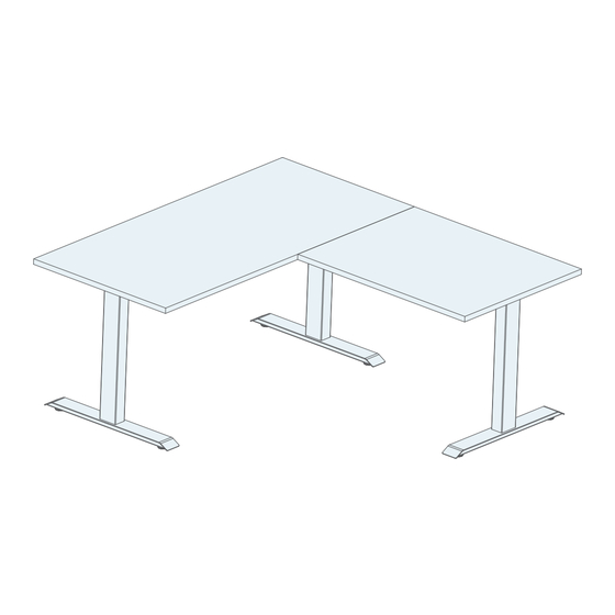
- Page 1 DESKY L-SHAPE SIT STAND DESK INSTRUCTION MANUAL ©2020 DESKY. All Rights Reserved...
- Page 2 Welcome! Thank you for choosing DESKY. We are so excited that you will be creating a healthier work environment with one of our ergonomically designed electric height adjustable desks! height adjustable desk technology that comes in each DESKY height adjustable desk.
-
Page 3: Table Of Contents
Safety Instructions Unpacking & Preparation Parts List & Tools Components Diagram Assembly Instructions Operating Controller Programming Controller Troubleshooting Warranty Info... -
Page 4: Safety Instructions
Instruction Manual may result in property damage, bodily injury or damage to the product itself. Before beginning assembly of your DESKY: Read and understand this Instruction Manual fully before attempting to assembly or operate the product. This is required to safely and properly operate the product. - Page 5 SAFETY INSTRUCTIONS Do not open any desk component or insert any object in a desk component. Risk of electric shock. Opening any desk component will void the product warranty. Keep fingers and all body parts clear of the moving desk and all moving components.
-
Page 6: Unpacking & Preparation
PREPARATION Check the parts list in this manual to ensure that all necessary components have been received. The DESKY Corner Desk components are shipped in two (3) seperate shipping boxes. Excluding the desktop. If you have also ordered a desktop from us we recommend leaving this in its shipping box until it is needed to avoid any damage to the surface finish. -
Page 7: Parts List & Tools
PARTS LIST & TOOLS BOX 1 A - CROSSBAR ENDS B - CROSSBAR RAILS C - SIDE BRACKETS QTY: 2 QTY: 2 QTY: 2 D - FOOT E - HEX KEY F - MACHINE SCREWS QTY: 2 QTY: 2 - Size 4 QTY: 38 - M6x14mm I - CABLE CLIPS G - GRUB SCREWS... - Page 8 PARTS LIST & TOOLS BOX 3 M - SIDE BRACKETS K - CROSSBAR END L - CROSSBAR RAILS QTY: 1 QTY: 2 QTY: 1 N - FOOT O - CONNECTING CROSS P - MACHINE SCREWS QTY: 1 QTY: 16 M6x14 QTY: 1 Q - TIMBER SCREWS R - HEX KEY...
-
Page 9: Components Diagram
COMPONENTS DIAGRAM... -
Page 10: Assembly Instructions
ASSEMBLY INSTRUCTIONS Step 1 Place the two Crossbar Ends (A) upside down so that the eight (8) machine grub screw holes (G) are facing upward as pictured. The Crossbar Rails (B) are located inside the Crossbar Ends (A) and will need to be removed and set aside for later steps. - Page 11 ASSEMBLY INSTRUCTIONS Step 3 Position the Side bracket (C) against the back of the Crossbar end (A) so that the four (4) holes in the sie bracket line up with the holes on the crossbar end. Insert four (4) Machine screws (F) and use the large Hex key (E) to screw in a few turns.
- Page 12 ASSEMBLY INSTRUCTIONS Step 5 Slide the two Crossbar rails (B) into the two Crossbar ends (A) to connect the frame assembly. Ensure the crossbar rails are orientated so the rail cut-outs face inward as shown. Step 6 Place your desktop upside down on a non-abrasive surface like a carpet or rug and place the frame on top.
- Page 13 ASSEMBLY INSTRUCTIONS Step 7 Your desktop will have pre-drilled holes or threaded screw inserts, depending on the desktop you have purchased from us. Desktops with threaded screw inserts: use eight (8) Machine screws (F) to secure the frame to the desktop. Desktops with pre-drilled holes: use eight (8) Timber screws (H) to secure the frame to the desktop.
- Page 14 ASSEMBLY INSTRUCTIONS Step 8 Use the Hex key (E) provided to insert and tighten each Grub screw (G ) on the Crossbar ends (A) and secure the Crossbar rails (B) in place. Step 9 Secure the Connecting Crossbar (R) to your assembled Cross Bar (A) using three machine screws (F).
- Page 15 ASSEMBLY INSTRUCTIONS Step 10 If you have purchased the Integrated Cable & Power Channel, secure one end to the Side bracket (C) as shown and extend the width of the channel to meet the other side bracket. Make sure the spring release knob is secrewed into the side bracket securely.
- Page 16 ASSEMBLY INSTRUCTIONS Step 12 with one person on each side of the main desk section, hold the Two person lift: desk top with one hand and the leg with the other. Carefully rotate the desk until the feet on the back side of the desk contact the floor. Ensure the desk is rotated backwards to avoid damage to the front mounted controller.
- Page 17 ASSEMBLY INSTRUCTIONS Step 13 After repeating steps 2-4 with the components found in the Third Leg Box (K,M,N,S). Attach the third leg assembly onto the connecting cross bar (O) using the center rails (L). Leave the third leg assembly section loose on the center rails, do not tighten any screws as you will need to align the desk top before securing the frame.
- Page 18 ASSEMBLY INSTRUCTIONS Step 14 Slide the smaller desktop section onto the frame. Align all of the pre-drilled threaded inserts with the holes on the frame. From the underside of the smaller desktop align all of the holes...
- Page 19 ASSEMBLY INSTRUCTIONS Step 15 Once the third leg assembly is aligned to the holes on the desktop secure the frame using 5 Machine Screws (F/S). If you are using your own desktop you can secure the frame using the provided Timber Screws (H/T). Step 16 Use the Hex key (E) provided to insert and tighten each Grub screw (G ) on the Connecting Crossbar (O) and the Crossbar End (K) locking the Crossbar Rails (L) in...
- Page 20 ©2020 DESKY. All Rights Reserved 40035028 A...
Need help?
Do you have a question about the L-SHAPE SIT STAND DESK and is the answer not in the manual?
Questions and answers