Table of Contents
Advertisement
Quick Links
Advertisement
Table of Contents

Subscribe to Our Youtube Channel
Related Manuals for Blueridge BP07B


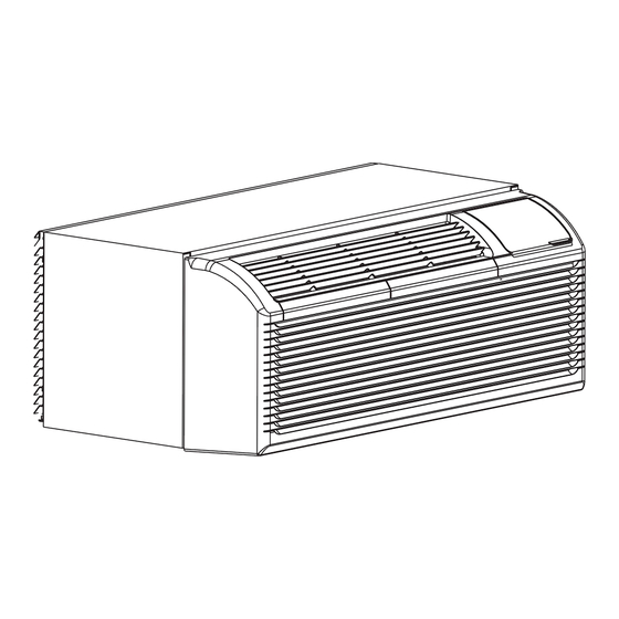
Summary of Contents for Blueridge BP07B
- Page 1 R32 PACKAGED TERMINAL AIR CONDITIONER/HEAT PUMP Owner’s Manual Model: BP07B BP09B BP12B BP15B PTAC Series IMPORTANT NOTE: North America Products Before using your appliance, please read this manual and SAFETY MANUAL(if any) carefully and keep it for future reference.
-
Page 2: Table Of Contents
CONTENTS Safety precautions Installation instructions Before you get start Before the installation Installation overview Customize your features Operation instructions Control Panel Care and Maintenance Troubleshooting... -
Page 3: Safety Precautions
Safety Precautions Must read the warning message. Inside you will find many helpful hints on how to use and maintain To prevent injury to the user or other people and property your air conditioner properly. Just a little preventive care on your damage, the following instructions must be followed. - Page 4 WARNING Plug in power plug properly. Otherwise, it may cause electric shock Unplug the unit if strange sounds, smell, or smoke or fire due to excess heat generation. Do not operate or stop the unit comes from it. It may cause fire and electric shock. by inserting or pulling out the power plug.It may cause electric shock Do not use the socket if it is loose or damaged.
- Page 5 CAUTION appliance by a person responsible for their safety. Hold the plug by the head of the power plug when taking Children should be supervised to ensure that they do not play it out. It may cause electric shock and damage. Turn o the with the appliance.
- Page 6 Operation of Current Device The power supply cord contains a current device that senses damage to the power cord. To test your power supply cord do the following: Plug in the Air Conditioner. The power supply cord will have TWO buttons on the plug head. Press the TEST button, you will notice a click as the RESET button pops out.
- Page 7 WARNING Electrical Information For Your Safety The complete electical rating of your new room air conditioner Do not store or use gasoline or other flammable vapors and is stated on the serial plate. Refer to the rating when checking liquids in the vicinity of this or any other appliance. the electrical requirements.
- Page 8 WARNING Electrical Requirements Observe all local governing codes and ordinances. Do not, under any circumstances, remove the power Electrical Shock and Personal Injury Hazard supply cord grounding prong. Electrical ground is required on this appliance. NOTE: If codes permit, and a separate grounding wire is used; DO NOT ground to a gas line.
-
Page 9: Before You Get Start
Before you get start Contents of the package and preparation What is in the Package n u a Unit Control panel sticker This unit is controlled by wall mounted thermostat Owner’s manual Subbase kit (for 265V model only, optional ) Subbase Cover panel I Cover panel II... -
Page 10: Before The Installation 0
Before the installation Preparations before installation The installation must be Installing your We recommend We’re here if you need us, n u a carried out in strict AC should take doing this with please contact your local accordance with the about 60 minutes. -
Page 11: Installation Overview 0
Installation overview Installation Completion Display Installing Unit into the wall Unit Outlet Air Intake Control panel cover NOTE Illustrations in this manual are for explanatory purposes. The actual shape of your unit may be slightly di erent. The actual shape shall prevail. - Page 12 Instructions Complete Unit installation NOTE Please doing this with a helper, or even two helpers. What you need.
- Page 13 Preparations for Unit Installation Drill Shipping here tape Drill here Fig.7 Pull out at the bottom to release Fig.6 it from the tabs, then lift the front panel up. Install the grille on the wall sleeve prior to installing the wall sleeve in the wall! Attach Wall sleeve.
- Page 14 Unit Installation Shipping Vent control lever screw Fig.8 Fig.9 Vent closed Vent open Install and fix the main part of the unit. Remove the shipping screw from the vent door. (See Fig.8) Rotate the vent control lever to either open or close the vent door. (See Fig.9) NOTE: CAUTION: Do not put obstacles around air-inlet or inside of air-outlet of...
- Page 15 Install the unit into the wall sleeve Fig.12 Fig.10 Fig.11 Write down or take a picture of the serial number prior to installing the unit into the wall sleeve. Install the unit into the wall sleeve Reinstall front panel. Lift unit level and slide unit into wall sleeve until firmly against front of Place tabs over top rail .
-
Page 16: Customize Your Features
Customize your features Product function reset operation NOTE Unit must be powered OFF to e ectively change their status. DIP SWITCHES CONFIGURATIONS Please refer to the following table for DIP SWITCHES CONFIGURATIONS operation. Pull out at the bottom to release it DIP Switches from the tabs, then lift the front panel up. - Page 17 Table 1 DIP SWITCHES CONFIGURATIONS UP(ON) DOWN(OFF) Remarks For Heat Pump unit only Electric Heat Only Electric Heat and Pump Heat Wall Thermostat Enable Control Panel Enable F~86 ° °F(16°C~30°C); Two configurations (S4*S5) UP*DOWN:65°F~78°F(18°C~26°C); S4*S5 combine to select set point DOWN*UP:63°F~80°F(17°C~27°C);...
- Page 18 DIP SWITCHES CONFIGURATIONS by PANEL CONTROL(Optional) NOTE Unit must be powered OFF to e ectively change their status. - Press the up and down buttons together for 3 seconds to activate the dip switches configurations by panel control (see Fig.4). - See Table 1 for Dip Switches configurations and functions by panel control.
- Page 19 Table1 —— DIP SWITCHES CONFIGURATIONS by PANEL CONTROL Low(right) High(left) Remarks 1-by panel control 0-by dip switches 1-electric heat only 0-electric heat and pump heat For Heat Pump unit only 3-use control panel or some types of wall thermostat; You can consult with the S3*S9 2-use other types of wall thermostat;...
- Page 20 WALL THERMOSTAT TERMINAL (Optional) IMPORTANT Only trained, qualified personnel should access electrical panel on unit and install electrical accessories. Please contact your local electrical contractor, dealer, or distributor for assistance. Thermostat Wire Routing Thermostat wire is field supplied. Recommended wire gauge is 18 to 20 gauge solid thermostat wire.
- Page 21 WALL THERMOSTAT TERMINAL (Optional) Terminal of some types of wall thermostat Dip switch Dip switch Installation instruction of some types of wall Thermostat (you can Consult with the sales agency or manufacturer for details) Pull the dip switch to the DOWN(OFF) Insert the wire connector of the wall thermostat into the relevant terminal position as shown below.
- Page 22 WALL THERMOSTAT TERMINAL (Optional) MODE B Wire color TERMINAL DESIGNATION FC(L) Front desk control terminal L Brown Front desk control terminal N Pink FC(N) LOW-FAN Low fan speed Purple Green HI-FAN High fan speed Remove the two screws 4-way valve; Reverse cycle (Energized in Blue 4-WAY Take the cover panel down...
- Page 23 WALL THERMOSTAT WIRING EXAMPLES...
- Page 24 NOTE: Use terminal 4-way for heat pump connection only. Suggest set the compressor protection time morn than 3 minutes in . If set less than 3 minutes, the compressor will restart delay 3 minutes still. Wall thermostat must be heating changeover 4-way valve. For thermostats that have only one fan speed output (on or auto),the fan speed is determined by how the terminal connector is wired.
-
Page 25: Operation Instructions
OPERATION INSTRUCTIONS Control Panel NOTE The control panel keypad will look like the following Fig.1. For some models with REMOTE SIGNAL RECEPTOR, the unit can be controlled by the control panel alone or by the remote. NOTE: Some models have no REMOTE SIGNAL RECEPTOR. Fig.1 Description POWER - Function... - Page 26 Description · HEAT:For heat pump models,the unit can alternate to run between in reverse cycle heat mode and electric heater mode according to the di erence between the setting temperature andthe room temperature. · The fan motor cycles with the compressor stop. DRY : In this mode, the air conditioner will generally operate in the form of a dehumidifier.
- Page 27 Description · Shows the set temperature in°C or°F. While on Fan only mode,it shows the room temperature. Control code (on some models): LC - Pads on the control panel is not available.The unit can be setted by using wire cotroller only. FC - Pads on the control panel and wire controller are not available.
-
Page 28: Care And Maintenance
CARE AND MAINTENANCE CAUTION • UNIT DAMAGE HAZARD Failure to follow this caution may result in equipment damge or improper operation. Airflow restriction may cause damage to the unit. FRONT PANEL AND CASE - Turn unit o and disconnect power supply. To clean, use water and a mild detergent. use bleach and abrasivers.Some commercial cleaners may damage the plastic parts. - Page 29 -Removing Air Filter -Replacing Air Filter 2 Air filters Pull up - To Clean Air Filters: Push down Vacuum o heavy soil. Run water through filter. Dry thoroughly before replacing. Fig. 13 Fig. 14 Vent door - VENT DOOR FILTER: control lever IMPORTANT:TURN UNIT OFF BEFORE CLEANING.
-
Page 30: Troubleshooting
TROUBLESHOOTING Before calling for service, review this list. It may save you time and money. This list includes common occurrences that are not the result of defective workman-ship or materials in this appliance. Problem Solution Unit may have become unplugged. Check that plug is plugged securely in wall receptacle. NOTE:Plug has a test/reset button on it.Make sure that the plug has not tripped. - Page 31 Problem Solution Low outdoor temperature. When outdoor temperature is approximately 55OF or below, ICE OR FROST frost may form on the indoor coil when unit is in Cooling mode.Switch unit to FAN operation until ice or frost melts. FORMS ON INDOOR COIL The filters are dirty.
Need help?
Do you have a question about the BP07B and is the answer not in the manual?
Questions and answers