Table of Contents

Subscribe to Our Youtube Channel
Related Manuals for EG4 LIFEPOWER4


Summary of Contents for EG4 LIFEPOWER4
- Page 1 S E R V E R R A C K Q U I C K - S T A R T G U I D E ©2024 EG4 ELECTRONICS, LLC. ALL RIGHTS RESERVED. VERSION 1.2 | INFORMATION SUBJECT TO CHANGE WITHOUT NOTICE. MODEL #: SR-48-100-LP4-IN-02...
-
Page 2: Table Of Contents
10.1 PROTOCOL ID DIP SWITCH ........................16 10.2 RS485 PROTOCOL AUTODETECTION ..................... 17 10.3 INSTALLING WITH DIFFERENT EG4 BATTERY MODELS ..............18 BMS TOOLS ................................20 11.1 INTRODUCTION TO THE BMS ........................20 11.2 BMS TOOLS INSTALLATION AND INTERFACING ................20 FIRMWARE UPDATES ............................ -
Page 3: Abbreviations
1. ABBREVIATIONS • In-lbs. – Inch Pounds AWG – American Wire Gauge • • kW – Kilowatt A – Amps • • kWh – Kilowatt-hour • Ah – Amp hour(s) • LCD – Liquid Crystal Display • AC – Alternating Current LFP –... -
Page 4: Technical Specifications
2. TECHNICAL SPECIFICATIONS MODULE OPERATING PARAMETERS PARAMETER RECOMMENDED 51.2V VOLTAGE 100Ah CAPACITY CHARGING VOLTAGE (BULK/ABSORB) 56.8V 44.8V 20%* SOC CUTOFF CHARGING CURRENT 100A (Max. continuous) DISCHARGING CURRENT 100A (Max. continuous) MAXIMUM CONTINUOUS DISCHARGE RATE 5.12kW NAMEPLATE ENERGY CAPACITY 5.12kWh BMS PARAMETERS CHARGE SPEC DELAY... - Page 5 -4°F – 122°F (-20°C – 50°C) STORAGE RANGE IP20 INGRESS PROTECTION STANDARDS AND CERTIFICATIONS UL 1973 ETL Recognized Component Certification MODULE UL9540A (Passed) UL9540 listed with 18kPV-12LV *EG4 recommends this value be set no lower than 20% to maintain the recommended 80% depth of discharge.
-
Page 6: Battery Safety
3. BATTERY SAFETY SAFETY INSTRUCTIONS Before any work begins, carefully read all safety instructions, and always observe them when working on or with the battery. The installation must follow all applicable national or local standards and regulations. Consult with the local AHJ to obtain the proper permits and permissions before installation. - Page 7 32°F, disconnect battery immediately and consult manufacturer. DISCLAIMER EG4 reserves the right to make changes to the material herein at any time without notice. Please refer to www.eg4electronics.com for the most updated version of our manuals/spec sheets.
-
Page 8: Ul 1973 Conditions Of Acceptability
Consideration should be given to the following when the component is used in or with another product. 1. The battery module SR-48-100-LP4-IN-02 (LifePower4 V2) had been evaluated based upon manufacturer’s specifications for charging, discharging and temperature limits. They have not been evaluated in combination with charger(s) or other control systems in the end use application. -
Page 9: Packing List
50% SOC (state of charge) before placing it in storage. Lithium batteries will lose a certain percentage of their total charge while in storage, depending on how long they are stored and the conditions they are stored in. EG4 recommends recharging the batteries after 8 – 9 months in prolonged storage. -
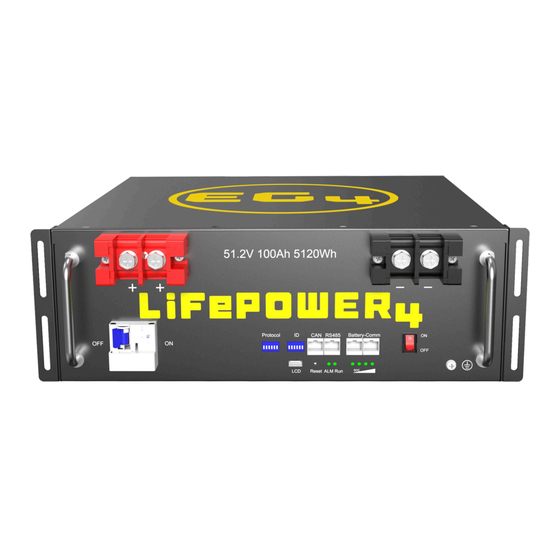
Page 10: Front Panel Callouts
7. FRONT PANEL CALLOUTS 7.1 BATTERY DIAGRAM ITEM DESCRIPTION REMARKS Secures the battery to the Rack mount ear For battery rack mounting rack Handle For carrying/handling battery Positive terminal M8 bolt (x2) Pin 4 – CAN_H CAN communication interface Pin 5 – CAN_L Pin 1 &... -
Page 11: Led Indicator Status & Definition
7.2 LED INDICATOR STATUS & DEFINITION SOC INDICATOR NORMAL/ NOTES STATUS ALARM/ PROTECTION SOC1~SOC4 Shutdown/Sleep Normal According to Stand-by the state Alarm FLASH before stand-by Normal Short flash Based on battery indicator Alarm Short flash Short flash (Each LED indicates 25% SOC) End-off Voltage Charge... -
Page 12: Installing The Battery
Where ambient temperature is above 86°F (30°C), cable size must be increased according to NEC 310. The 4 AWG cable included in the package is intended only for the connection from the battery module to an EG4 battery rack busbar. DANGER! When adding or removing a battery from any rack, cabinet, or busbar, turn off ALL batteries, and use a voltmeter to confirm there is no voltage present. - Page 13 CAUTION: Never position the battery upside down or face down! Acceptable Acceptable Best...
-
Page 14: Installation In Eg4 Battery Rack
Use the included battery cables or size the battery cables appropriately! Refer to an NEC approved ampacity chart for specifications. NOTE: EG4 recommends using a properly sized (amp rated) busbar to parallel batteries together. Paralleling via the battery terminals will cause inconsistent charging and discharging issues in the bank. -
Page 15: Battery Communications
® as possible in the simplest manner. EG4 Electronics includes the option of connecting the battery to PC software to monitor the module status. This enables users to monitor and comprehend the battery’s performance and to troubleshoot any issues that may occur. -
Page 16: Communication Cable Pinout And Dip Switch Id Tables
9.2 COMMUNICATION CABLE PINOUT AND DIP SWITCH ID TABLES LifePower4 48V V2 batteries interface with an inverter by designating a “Host” battery (DIP ® switch ID No. 1). The ID code range is 1 ‒ 64 and the communication mode can support up to 64 modules in parallel. -
Page 17: Protocol Change/Selection Procedure
The inverter protocol ID is used for establishing closed-loop communications with supported inverters. The inverters listed in chart 10.1 are capable of closed-loop communications with the battery. All other inverters will not support closed-loop communications with LifePower4 V2 batteries. 1. Power off all battery DC breakers and BMS power buttons. Ensure that the voltage between positive and negative busbars is 0V. -
Page 18: Protocol Select
In the “OFF” position, this allows the battery to communicate with Simplified LINK protocol version 1 LL’s and original LifePower4 with the Multipack firmware. NOTE: The Complete Link Protocol and the Simplified Link Protocol will ONLY work with CAN communication, not RS485. -
Page 19: Rs485 Protocol Autodetection
10.2 RS485 PROTOCOL AUTODETECTION NOTE: When using RS485 communications, the battery will auto detect the inverter protocol being used. CODE DIP SWITCH POSITION BRAND COMMUNICATIONS RS485 Growatt RS485 Schneider RS485 Note: Confirm that the RS485 cable being used is pinned correctly in respect to the inverter being used. DESCRIPTION RS485-B RS485-A... -
Page 20: Installing With Different Eg4 Battery Models
100% before paralleling them together. This step is crucial to optimize battery performance and ensure proper operation. If communicating multiple EG4 batteries together, the Multipack firmware will need to be used via an RS485 Update. For the example below, all batteries will need to be updated EXCEPT the EG4 LifePower V2. - Page 21 RS485-A NOTE: When using LL-V1 and LifePower4 batteries in communications with the LL-S/LL-V2 multi-pack firmware, ensure the communications cable between the LL-V2 and all older model batteries down are pinned to this standard. If there are extra pins populated, the LL-S will trip its breaker if it receives a signal from pins 3 or 6 along with all other batteries in this parallel configuration.
-
Page 22: Bms Tools
The BMS is intended to safeguard the battery and battery cells against a variety of situations that could damage or destroy system components. This protection also aids in keeping the battery and battery cells operational for a greater number of life cycles. Each EG4 LifePower4 battery is ®... -
Page 23: Firmware Updates
When the ALM light on the battery control panel is on, it means that the battery has given an alarm or has been protected from potential damage. Please check the cause of the failure through EG4 Monitor Center or BMS Tools and take appropriate measures or go directly to the battery site to troubleshoot. - Page 24 Other Common Faults and Solutions FAULT ANALYSIS ACTION Select proper “host” battery DIP Check communication port connection Inverter communication failure switch address, and power cycle the and battery ID setting. battery. Open breaker, or battery voltage is too Check battery breaker and/or No DC output low.
-
Page 25: Long Term Maintenance
There are several websites and organizations that will accept this battery to recycle at little to no cost to the user. At EG4, we understand that we are working with customers across the United States and the world. Our recommendation is to go online and search the term “Lithium Battery Disposal Near Me.”... -
Page 26: Eg4 10-Year Limited Warranty
Damages incurred from a voltage or current spikes due to open-loop lithium battery communications EG4 product warranty is a limited warranty – EG4 limits its liability in the event of a product defect to repair or replacement in accordance with the terms of this limited warranty. EG4 is not responsible for any additional or indirect damages that may arise from the malfunctioning of the product. - Page 27 C H A N G E L O G Version 1.2 Added Section 4, UL 1973 Conditions of Acceptability • Added RS485 Protocol Autodetection Section 10.2 • Version 1.1 Modified cell information and certifications • Modified verbiage on cover page •...
- Page 28 CONTACT US support@eg4electronics.com (903) 609-1988 www.eg4electronics.com...
Need help?
Do you have a question about the LIFEPOWER4 and is the answer not in the manual?
Questions and answers