Table of Contents
Advertisement
Quick Links
Advertisement
Table of Contents

Related Manuals for Honeywell N668X


Summary of Contents for Honeywell N668X
- Page 1 N668X Decoded Engine User’s Guide...
- Page 2 Disclaimer Honeywell International Inc. (“HII”) reserves the right to make changes in specifications and other information contained in this document without prior notice, and the reader should in all cases consult HII to determine whether any such changes have been made.
-
Page 3: Table Of Contents
® Verifone Ruby Terminal Default Settings ..............2-4 ® Gilbarco Terminal Default Settings ................2-4 Honeywell Bioptic Aux Port Configuration..............2-4 © Datalogic™ Magellan Aux Port Configuration..............2-4 NCR Bioptic Aux Port Configuration ................2-5 Wincor Nixdorf Terminal Default Settings ..............2-5 Wincor Nixdorf Beetle™ Terminal Default Settings ............2-5 Wincor Nixdorf RS232 Mode A ..................2-6... - Page 4 RS232 Modifiers ........................ 2-17 RS232 Baud Rate......................2-17 RS232 Word Length: Data Bits, Stop Bits, and Parity ..........2-18 RS232 Receiver Time-Out................... 2-19 RS232 Handshaking....................2-19 RS232 Timeout......................2-20 XON/XOFF ........................2-20 ACK/NAK ........................2-21 RS232 Stop Mode ....................... 2-21 Scanner to Bioptic Communication ...................
- Page 5 Poor Quality Codes ......................3-12 Poor Quality 1D Codes ....................3-12 Poor Quality PDF Codes ..................... 3-12 Image Snap and Ship ......................3-12 Hands Free Time-Out......................3-13 Reread Delay........................3-13 User-Specified Reread Delay .................... 3-13 2D Reread Delay ....................... 3-14 Illumination Lights......................
- Page 6 Add a Data Format ......................5-1 Other Programming Selections..................5-2 Terminal ID Table ........................ 5-3 Data Format Editor Commands................... 5-3 Move Commands......................5-6 Search Commands ......................5-7 Miscellaneous Commands..................... 5-9 Data Formatter ........................5-12 Data Format Non-Match Error Tone ................5-13 Primary/Alternate Data Formats ..................
- Page 7 GS1 DataBar Expanded ....................6-32 Trioptic Code ........................6-32 Codablock A ........................6-33 Codablock F ........................6-34 Label Code ........................6-34 PDF417 ..........................6-35 PDF417 Code Page..................... 6-35 MacroPDF417 ........................6-35 MicroPDF417........................6-36 GS1 Composite Codes...................... 6-36 UPC/EAN Version......................6-37 GS1 Emulation ........................
- Page 8 Show Scan Driver Revision ....................9-1 Show Software Revision...................... 9-1 Show Data Format....................... 9-1 Test Menu..........................9-2 TotalFreedom ........................9-2 Application Plug-Ins (Apps) ....................9-2 EZConfig-Scanning Introduction..................9-3 Installing EZConfig-Scanning from the Web..............9-3 Resetting the Factory Defaults .................... 9-4 Chapter 10 - Serial Programming Commands Conventions........................
- Page 9 For our latest contact information, please check our website at the link above. Product Service and Repair Honeywell International Inc. provides service for all of its products through service centers throughout the world. To obtain warranty or non-warranty service, please visit www.honeywellaidc.com...
- Page 10 viii...
-
Page 11: Chapter 1 - Getting Started
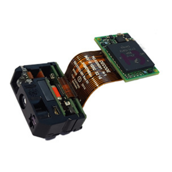
Introduction The N668X decoded out engine is a miniature, CMOS imager-based image capture and bar code imaging module device. It is configured to be sold as the optics module and decoder board separately with a board to board connection or board to ZIF con- nection. -
Page 12: Connecting The Development Scan Engine To The Pc
Connecting the Development Scan Engine to the PC The development OEM scan engine can connect to a PC for evaluation using the Honeywell interface board. There are two interface boards available: • Board to board interface board P/N 50125984-001 • Board to ZIF interface board P/N 50126046-001... -
Page 13: Board To Board-Usb Interface
Board to Board—USB Interface Note: For USB interface you must install the USB driver before connecting your scan engine. Download the driver from the Honeywell website at www.honeywellaidc.com. 1. Set the switch on the interface board to ON as shown below. -
Page 14: Board To Board-Rs232 Serial Port Interface
Board to Board—RS232 Serial Port Interface 1. Connect the serial interface cable (CBL-020-300-C00) to the interface board and to the computer. 2. Set the switch on the interface board to off as shown below. 3. Connect the power supply connector to the serial interface cable. Plug in the power supply. The engine powers-up and emits a series of beeps from low to high. -
Page 15: Board To Zif-Usb Interface
Board to ZIF—USB Interface 6. Set switch 2 on the interface board to off. 7. Connect the USB interface cable (CBL-500-300-S00) to the interface board and to a USB port on the computer. The engine powers-up and emits a series of beeps from low to high. 8. -
Page 16: Board To Zif-Rs232 Serial Port Interface
Board to ZIF—RS232 Serial Port Interface 1. Connect the serial interface cable (CBL-020-300-C00) to the interface board and to the computer. 2. Set the switch on the interface board to ON as shown below. 3. Connect the power supply connector to the serial interface cable. Plug in the power supply. The engine powers-up and emits a series of beeps from low to high. -
Page 17: Reading Techniques
Menu Bar Code Security Settings Honeywell scan engines are programmed by scanning menu bar codes or by sending serial commands to the scan engine. If you want to restrict the ability to scan menu codes, you can use the Menu Bar Code Security settings. Contact the nearest tech-... -
Page 18: Resetting The Custom Defaults
you want the beeper volume set to High, just scan the Set Custom Defaults bar code, then scan the Beeper Volume High menu code, and then Save Custom Defaults. The rest of the custom defaults will remain, but the beeper volume setting will be updated. -
Page 19: Chapter 2 - Programming The Interface
Programming the Interface Introduction This chapter describes how to program your system for the desired interface. Programming the Interface Use the following configuration bar codes to program the interface. Note: After you scan one of the codes, power cycle the host terminal to have the interface in effect. RS232 Serial Port The RS232 Interface bar code is used when connecting to the serial port of a PC or terminal. -
Page 20: Usb Ibm Surepos
USB IBM SurePos Scan one of the following “Plug and Play” codes to program the scan engine for an IBM SurePos (USB handheld scanner) or IBM SurePos (USB tabletop scanner) interface. Note: After scanning one of these codes, you must power cycle the cash register. USB IBM SurePos (USB Handheld Scanner) Interface... -
Page 21: Usb Serial
Scan the following code to program the scan engine to emulate a regular RS232-based COM Port. If you are using a Micro- soft® Windows® PC, you will need to download a driver from the Honeywell website (www.honeywellaidc.com). The driver will use the next available COM Port number. Apple® Macintosh computers recognize the scan engine as a USB CDC class device and automatically use a class driver. -
Page 22: Verifone ® Ruby Terminal Default Settings
Honeywell Bioptic Aux Port Configuration Scan the following Plug and Play code to program the scan engine for a Honeywell bioptic scanner auxiliary port configura- tion. This bar code sets the baud rate to 38400 bps and the data format to 8 data bits, no parity, 1 stop bit. -
Page 23: Ncr Bioptic Aux Port Configuration
NCR Bioptic Aux Port Configuration Scan the following Plug and Play code to program the scan engine for an NCR bioptic scanner auxiliary port configuration. The following prefixes are programmed for each symbology: Symbology Prefix Symbology Prefix UPC-A Code 39 UPC-E Interleaved 2 of 5 EAN-8... -
Page 24: Wincor Nixdorf Rs232 Mode A
Wincor Nixdorf RS232 Mode A Scan the following Plug and Play code to program the scanner for a Wincor Nixdorf RS232 Mode A terminal. This bar code sets the baud rate to 9600 bps and the data format to 8 data bits, odd parity, 1 stop bit. The following prefixes are pro- grammed for each symbology: Symbology Prefix... -
Page 25: Keyboard Country Layout
Keyboard Country Layout If your interface is USB Keyboard or Keyboard Wedge, your keyboard layout default is a US keyboard. To change this layout, refer to the chart below for your keyboard country. Scan the appropriate bar code below to change the layout. By default, national character replacements are used for the following characters: #$@[\]^‘{|}~ See ISO 2022/ISO 646 Character Replacements... - Page 26 Keyboard Countries (Continued) Bulgaria (Latin) Canada (French legacy) Canada (French) Canada (Multilingual) Croatia Czech Czech (Programmers) Czech (QWERTY) Czech (QWERTZ) Denmark Dutch (Netherlands) 2 - 8...
- Page 27 Keyboard Countries (Continued) Estonia Faroese Finland France Gaelic Germany Greek Greek (220 Latin) Greek (220) Greek (319 Latin) Greek (319) 2 - 9...
- Page 28 Keyboard Countries (Continued) Greek (Latin) Greek (MS) Greek (Polytonic) Hebrew Hungarian (101 key) Hungary Iceland Irish Italian (142) Italy Japan ASCII 2 - 10...
- Page 29 Keyboard Countries (Continued) Kazakh Kyrgyz (Cyrillic) Latin America Latvia Latvia (QWERTY) Lithuania Lithuania (IBM) Macedonia Malta Mongolian (Cyrillic) Norway 2 - 11...
- Page 30 Keyboard Countries (Continued) Poland Polish (214) Polish (Programmers) Portugal Romania Russia Russian (MS) Russian (Typewriter) Serbia (Cyrillic) Serbia (Latin) 2 - 12...
- Page 31 Keyboard Countries (Continued) Slovakia Slovakia (QWERTY) Slovakia (QWERTZ) Slovenia Spain Spanish variation Sweden Switzerland (French) Switzerland (German) Tatar Turkey F 2 - 13...
-
Page 32: Keyboard Style
Keyboard Countries (Continued) Turkey Q Ukrainian United Kingdom United States (Dvorak) United States (Dvorak left) United Stated (Dvorak right) United States (International) Uzbek (Cyrillic) Keyboard Style This programs keyboard styles, such as Caps Lock and Shift Lock. If you have used Keyboard Conversion settings, they will override any of the following Keyboard Style settings. -
Page 33: Keyboard Conversion
Shift Lock is used when you normally have the Shift Lock key on (not common to U.S. keyboards). Shift Lock Automatic Caps Lock is used if you change the Caps Lock key on and off. The software tracks and reflects if you have Caps Lock on or off. -
Page 34: Control Character Output
Control Character Output This selection sends a text string instead of a control character. For example, when the control character for a carriage return is expected, the output would display [CR] instead of the ASCII code of 0D. Refer to ASCII Conversion Chart (Code Page 1252) on page A-3. -
Page 35: Rs232 Modifiers
* Turbo Mode Off Numeric Keypad Mode: Sends numeric characters as if entered from a numeric keypad. Default = Off Numeric Keypad Mode On * Numeric Keypad Mode Off Automatic Direct Connect Mode: This selection can be used if you have an IBM AT style terminal and the system is dropping characters. -
Page 36: Rs232 Word Length: Data Bits, Stop Bits, And Parity
2400 4800 9600 19200 38400 57,600 * 115,200 RS232 Word Length: Data Bits, Stop Bits, and Parity Data Bits sets the word length at 7 or 8 bits of data per character. If an application requires only ASCII Hex characters 0 through 7F decimal (text, digits, and punctuation), select 7 data bits. -
Page 37: Rs232 Receiver Time-Out
7 Data, 2 Stop, Parity Even 7 Data, 2 Stop Parity None 7 Data, 2 Stop, Parity Odd 8 Data, 1 Stop, Parity Even * 8 Data, 1 Stop, Parity None 8 Data, 1 Stop, Parity Odd 8 Data, 1 Stop, Parity Mark RS232 Receiver Time-Out The unit stays awake to receive data until the RS232 Receiver Time-Out expires. -
Page 38: Rs232 Timeout
Flow Control with Timeout: The scan engine asserts RTS when it has data to send and waits for a delay (see RS232 Timeout on page 2-20) for CTS to be asserted by the host. If the delay time expires and CTS is not asserted, the device transmit buffer is cleared and scanning may resume. -
Page 39: Ack/Nak
Scanner to Bioptic Communication The following settings are used to set up communication between Honeywell scan engines and bioptic scanners. Note: The scan engine’s baud rate must be set to 38400 and the RS232 timeout must be set to 3000 in order to communicate with a bioptic scanner. -
Page 40: Scanner-Bioptic Ack/Nak Mode
Scanner-Bioptic ACK/NAK Mode Bioptic ACK/NAK On must be scanned so the scan engine will wait for an ACK or NAK from a bioptic scanner after each packet is sent. The Scanner-Bioptic ACK/NAK Timeout (below) controls how long the scanner will wait for a response. Default = Bioptic ACK/NAK Off. -
Page 41: Chapter 3 - Input/Output Settings
Input/Output Settings Power Up Beeper The scan engine can be programmed to beep when it’s powered up. Scan the Off bar code(s) if you don’t want a power up beep. Default = Power Up Beeper On - Scanner. Power Up Beeper Off - Scanner * Power Up Beeper On - Scanner... -
Page 42: Good Read And Error Indicators
Good Read and Error Indicators Beeper – Good Read The beeper may be programmed On or Off in response to a good read. Turning this option off only turns off the beeper response to a good read indication. All error and menu beeps are still audible. Default = Beeper - Good Read On. Beeper - Good Read Off * Beeper - Good Read On Beeper Volume –... -
Page 43: Beeper Pitch - Error
High (4200 Hz) Beeper Pitch – Error The beeper pitch codes modify the pitch (frequency) of the sound the scan engine emits when there is a bad read or error. Default = Razz. * Razz (250 Hz) Medium (3250 Hz) High (4200 Hz) Beeper Duration –... -
Page 44: Number Of Beeps - Good Read
Number of Beeps – Good Read The number of beeps of a good read can be programmed from 1 - 9. The same number of beeps will be applied to the beeper and LED in response to a good read. For example, if you program this option to have five beeps, there will be five beeps and five LED flashes in response to a good read. -
Page 45: Manual Trigger Modes
Manual Trigger Modes When in manual trigger mode, the scanner scans until a bar code is read, or until the trigger is released. Two modes are avail- able, Normal and Enhanced. Normal mode offers good scan speed and the longest working ranges (depth of field). Enhanced mode will give you the highest possible scan speed but slightly less range than Normal mode. -
Page 46: Character Activation Mode
Character Activation Mode You may use a character sent from the host to trigger the scan engine to begin scanning. When the activation character is received, the scan engine continues scanning until either the Character Activation Timeout (page 3-7), the deactivation charac- ter is received (see Deactivation Character on page 3-7), or a bar code is transmitted. -
Page 47: Character Activation Timeout
Character Activation Timeout You can set a timeout for the length of time the illumination remains on and attempting to decode bar codes when using Character Activation Mode. Set the length (in milliseconds) for a timeout by scanning the following bar code, then setting the timeout (from 1-300,000 milliseconds) by scanning digits from the Programming Chart inside the back cover of this... -
Page 48: Mobile Phone Read Mode
Mobile Phone Read Mode When this mode is selected, your scan engine is optimized to read bar codes from mobile phone or other LED displays. How- ever, the speed of scanning printed bar codes may be slightly lower when this mode is enabled. You can enable Mobile Phone Reading for either a hand held device, or for a hands-free (presentation) application. -
Page 49: Presentation Led Behavior After Decode
Presentation LED Behavior after Decode When a scan engine is in presentation mode, the LEDs dim 30 seconds after a bar code is decoded. If you wish to dim the LEDs immediately after a bar code is decoded, scan the LEDs Off bar code, below. Default = LEDs On. * LEDs On LEDs Off Presentation Sensitivity... - Page 50 Bar Code 1 Bar Code 2 100% Note: A bar code needs only to be touched by the centering window in order to be read. It does not need to pass completely through the centering window. Scan Presentation Centering On, then scan one of the following bar codes to change the top, bottom, left, or right of the centering window.
-
Page 51: Codegate
Right of Presentation Centering Window ® CodeGate When CodeGate is On, the trigger is used to allow decoded data to be transmitted to the host system. The scanner remains on, scanning and decoding bar codes, but the bar code data is not transmitted until the trigger is pressed. When CodeGate is Off, bar code data is transmitted when it is decoded. -
Page 52: Poor Quality Codes
Poor Quality Codes Poor Quality 1D Codes This setting improves the scanner’s ability to read damaged or badly printed linear bar codes. When Poor Quality 1D Reading On is scanned, poor quality linear bar code reading is improved, but the scanner’s snappiness is decreased, mak- ing it less aggressive when reading good quality bar codes. -
Page 53: Hands Free Time-Out
Hands Free Time-Out The Scan Stand and Presentation Modes are referred to as “hands free” modes. If the scanner’s trigger is pulled when using a hands free mode, the scanner changes to manual trigger mode. You can set the time the scanner should remain in manual trig- ger mode by setting the Hands Free Time-Out. -
Page 54: 2D Reread Delay
2D Reread Delay Sometimes 2D bar codes can take longer to read than other bar codes. If you wish to set a separate Reread Delay for 2D bar codes, scan one of the programming codes that follows. 2D Reread Delay Off indicates that the time set for Reread Delay used for both 1D and 2D bar codes. -
Page 55: Aimer Delay
Aimer Delay The aimer delay allows a delay time for the operator to aim the scan engine before the picture is taken. Use these codes to set the time between when the trigger is pulled and when the picture is taken. During the delay time, the aiming light will appear, but the LEDs won’t turn on until the delay time is over. - Page 56 In the example below, the white box is the centering window. The centering window has been set to 8% top and 25% bottom. Since Bar Code 1 passes through the centering window, it will be read. Bar Code 2 does not pass through the centering window, so it will not be read.
-
Page 57: Preferred Symbology
Preferred Symbology The scan engine can be programmed to specify one symbology as a higher priority over other symbologies in situations where both bar code symbologies appear on the same label, but the lower priority symbology cannot be disabled. For example, you may be using the scanner in a retail setting to read U.P.C. symbols, but have occasional need to read a code on a drivers license. -
Page 58: Preferred Symbology Time-Out
Preferred Symbology Time-out Once you have enabled Preferred Symbology and entered the high and low priority symbologies, you must set the time-out period. This is the period of time the scan engine will search for a high priority bar code after a low priority bar code has been encountered. - Page 59 Output Sequence Example In this example, you are scanning Code 93, Code 128, and Code 39 bar codes, but you want the scanner to output Code 39 1st, Code 128 2nd, and Code 93 3rd, as shown below. Note: Code 93 must be enabled to use this example. A - Code 39 B - Code 128 C - Code 93...
-
Page 60: Output Sequence Editor
Output Sequence Editor Enter Sequence Default Sequence Partial Sequence If an output sequence operation is terminated before all your output sequence criteria are met, the bar code data acquired to that point is a “partial sequence.” Scan Discard Partial Sequence to discard partial sequences when the output sequence operation is terminated before completion. -
Page 61: Multiple Symbols
Multiple Symbols When this programming selection is turned On, it allows you to read multiple symbols with a single pull of the scanner’s trigger. If you press and hold the trigger, aiming the scanner at a series of symbols, it reads unique symbols once, beeping (if turned on) for each read. -
Page 62: Working Orientation
VIDREV0. * Video Reverse Off Working Orientation Some bar codes are direction-sensitive. For example, KIX codes and OCR can misread when scanned sideways or upside down. Use the working orientation settings if your direction-sensitive codes will not usually be presented upright to the scanner. Default = Upright. -
Page 63: Chapter 4 - Data Editing
Data Editing Prefix/Suffix Overview When a bar code is scanned, additional information is sent to the host computer along with the bar code data. This group of bar code data and additional, user-defined data is called a “message string.” The selections in this section are used to build the user-defined data into the message string. -
Page 64: To Clear One Or All Prefixes Or Suffixes
Example: Add a Tab Suffix to All Symbologies Step 1. Scan Add Suffix. Step 2. Scan 9, 9 from the Programming Chart inside the back cover of this manual to apply this suffix to all symbologies. Step 3. Scan 0, 9 from the Programming Chart inside the back cover of this manual. -
Page 65: Function Code Transmit
Clear One Suffix Clear All Suffixes Function Code Transmit When this selection is enabled and function codes are contained within the scanned data, the scan engine transmits the func- tion code to the terminal. Charts of these function codes are provided in Supported Interface Keys starting on page... -
Page 66: Interfunction Delay
Next, scan the Character to Trigger Delay bar code, then the 2-digit hex value for the ASCII character that will trigger the delay ASCII Conversion Chart (Code Page 1252), beginning on page A-3. Delay Length Character to Trigger Delay To remove this delay, scan the Delay Length bar code, and set the number of delays to 0. Scan the Save bar code using Programming Chart inside the back cover of this manual. -
Page 67: Chapter 5 - Data Formatting
Data Formatting Data Format Editor Introduction You may use the Data Format Editor to change the scan engine’s output. For example, you can use the Data Format Editor to insert characters at certain points in bar code data as it is scanned. The selections in the following pages are used only if you wish to alter the output. -
Page 68: Other Programming Selections
Step 5. Length Specify what length (up to 9999 characters) of data will be acceptable for this symbology. Scan the four digit data length from the Programming Chart inside the back cover of this manual. For example, 50 characters is entered as 0050. Note: 9999 indicates all lengths. -
Page 69: Terminal Id Table
Terminal ID Table Terminal Model(s) Terminal ID PC keyboard (HID) Mac Keyboard PC Keyboard (Japanese) Serial (COM driver required) HID POS USB SurePOS Handheld USB SurePOS Tabletop Serial RS232 TTL RS232 True RS485 (IBM-HHBCR 1+2, 46xx) Keyboard PS2 compatibles AT compatibles Data Format Editor Commands When working with the Data Format Editor, a virtual cursor is moved along your input data string. - Page 70 F1 is the “Send all characters” command 0D is the hex value for a CR The data is output as: 1234567890 ABCDEFGHIJ <CR> Send all characters up to a particular character F3 Include in the output message all characters from the input message, starting with the character at the current cursor position and continuing to, but not including, the search character “ss,”...
- Page 71 <CR> Insert symbology name B3 Insert the name of the bar code’s symbology in the output message, without moving the cursor. Only symbologies with a Honeywell ID are included (see Symbology Charts on page A-1). Refer to the ASCII Conversion Chart (Code Page 1252), beginning on page A-3 for decimal, hex and character codes.
-
Page 72: Move Commands
Insert bar code length B4 Insert the bar code’s length in the output message, without moving the cursor. The length is expressed as a numeric string and does not include leading zeroes. B3 and B4 Example: Insert the symbology name and length Send the symbology name and length before the bar code data from the bar code above. -
Page 73: Search Commands
F5 Example: Move the cursor forward and send the data Move the cursor forward 3 characters, then send the rest of the bar code data from the bar code above. End with a car- riage return. Command string: F503F10D F5 is the “Move the cursor forward a number of characters” command 03 is the number of characters to move the cursor F1 is the “Send all characters”... - Page 74 F8 Example: Send bar code data that starts after a particular character Search for the letter “D” in bar codes and send all the data that follows, including the “D.” Using the bar code above: Command string: F844F10D F8 is the “Search forward for a character” command 44 is the hex value for “D”...
-
Page 75: Miscellaneous Commands
E6 Example: Remove zeroes at the beginning of bar code data This example shows a bar code that has been zero filled. You may want to ignore the zeroes and send all the data that follows. E6 searches forward for the first character that is not zero, then sends all the data after, followed by a carriage return. - Page 76 Replace characters E4 Replaces up to 15 characters in the output message, without moving the cursor. Replacement continues until the E5 command is encountered. Syntax = E4nnxx ...zz where nn is the total count of the number of characters in the list (characters to be replaced plus replacement characters); xx defines characters to be replaced and xx defines replacement characters, continuing through zz...
- Page 77 If this bar code is read, the next data format, if there is one, will be used on the data. If there is no other format, the format fails and the raw data is output as AB1234. If this bar code is read: the data is output as: 1234AB <CR>...
-
Page 78: Data Formatter
Data Formatter When Data Formatter is turned Off, the bar code data is output to the host as read, including prefixes and suffixes. Data Formatter Off You may wish to require the data to conform to a data format you have created and saved. The following settings can be applied to your data format: Data Formatter On, Not Required, Keep Prefix/Suffix Scanned data is modified according to your data format, and prefixes and suffixes are transmitted. -
Page 79: Data Format Non-Match Error Tone
Data Format Non-Match Error Tone When a bar code is encountered that doesn’t match your required data format, the scan engine normally generates an error tone. However, you may want to continue scanning bar codes without hearing the error tone. If you scan the Data Format Non-Match Error Tone Off bar code, data that doesn’t conform to your data format is not transmitted, and no error tone will sound. - Page 80 For example, you may have set your device to the data format you saved as Data Format 3. You can switch to Data Format 1 for a single trigger pull by scanning the Single Scan-Data Format 1 bar code below. The next bar code that is scanned uses Data Format 1, then reverts back to Data Format 3.
-
Page 81: All Symbologies
Symbologies This programming section contains the following menu selections. Refer to Chapter 10 for settings and defaults. • All Symbologies • Interleaved 2 of 5 • Aztec Code • Korea Post • China Post (Hong Kong 2 of 5) • Matrix 2 of 5 •... -
Page 82: Codabar
EXAMPLE: Decode only those bar codes with a count of 15 characters. Min. length = 15Max. length = 15 For a value other than the minimum and maximum message length defaults, scan the bar codes included in the explanation of the symbology, then scan the digit value of the message length and Save bar codes on the Programming Chart inside the back... -
Page 83: Codabar Concatenation
Validate Modulo 16, but Don’t Transmit Validate Modulo 16 and Transmit Codabar Concatenation Codabar supports symbol concatenation. When you enable concatenation, the scanner looks for a Codabar symbol having a “D” start character, adjacent to a symbol having a “D” stop character. In this case the two messages are concatenated into one with the “D”... -
Page 84: Code 39
Code 39 < Default All Code 39 Settings > Code 39 On/Off * On Code 39 Start/Stop Characters Start/Stop characters identify the leading and trailing ends of the bar code. You may either transmit, or not transmit Start/ Stop characters. Default = Don’t Transmit. Transmit * Don’t Transmit Code 39 Check Character... -
Page 85: Code 32 Pharmaceutical (Paraf)
Code 39 Message Length Scan the bar codes below to change the message length. Refer to Message Length Description (page 6-1) for additional information. Minimum and Maximum lengths = 0-48. Minimum Default = 0, Maximum Default = 48. Minimum Message Length Maximum Message Length Code 39 Append This function allows the scanner to append the data from several Code 39 bar codes together before transmitting them to... -
Page 86: Full Ascii
Full ASCII If Full ASCII Code 39 decoding is enabled, certain character pairs within the bar code symbol will be interpreted as a single character. For example: $V will be decoded as the ASCII character SYN, and /C will be decoded as the ASCII character #. Default = Off. -
Page 87: Interleaved 2 Of 5
Interleaved 2 of 5 < Default All Interleaved 2 of 5 Settings > Interleaved 2 of 5 On/Off * On Check Digit No Check Digit indicates that the scanner reads and transmits bar code data with or without a check digit. When Check Digit is set to Validate, but Don’t Transmit, the unit only reads Interleaved 2 of 5 bar codes printed with a check digit, but will not transmit the check digit with the scanned data. -
Page 88: Nec 2 Of 5
Maximum Message Length NEC 2 of 5 < Default All NEC 2 of 5 Settings > NEC 2 of 5 On/Off * On Check Digit No Check Digit indicates that the scanner reads and transmits bar code data with or without a check digit. When Check Digit is set to Validate, but Don’t Transmit, the unit only reads NEC 2 of 5 bar codes printed with a check digit, but will not transmit the check digit with the scanned data. -
Page 89: Code 93
NEC 2 of 5 Message Length Scan the bar codes below to change the message length. Refer to Message Length Description (page 6-1) for additional information. Minimum and Maximum lengths = 2-80. Minimum Default = 4, Maximum Default = 80. Minimum Message Length Maximum Message Length Code 93... -
Page 90: Code 93 Code Page
Code 93 Append This function allows the scanner to append the data from several Code 93 bar codes together before transmitting them to the host computer. When this function is enabled, the scanner stores those Code 93 bar codes that start with a space (excluding the start and stop symbols), and does not immediately transmit the data. -
Page 91: Straight 2 Of 5 Industrial (Three-Bar Start/Stop)
Straight 2 of 5 Industrial (three-bar start/stop) <Default All Straight 2 of 5 Industrial Settings> Straight 2 of 5 Industrial On/Off * Off Straight 2 of 5 Industrial Message Length Scan the bar codes below to change the message length. Refer to Message Length Description (page 6-1) for additional information. -
Page 92: Straight 2 Of 5 Iata (Two-Bar Start/Stop)
Straight 2 of 5 IATA (two-bar start/stop) <Default All Straight 2 of 5 IATA Settings> Straight 2 of 5 IATA On/Off * Off Straight 2 of 5 IATA Message Length Scan the bar codes below to change the message length. Refer to Message Length Description (page 6-1) for additional information. -
Page 93: Matrix 2 Of 5
Matrix 2 of 5 <Default All Matrix 2 of 5 Settings> Matrix 2 of 5 On/Off * Off Matrix 2 of 5 Message Length Scan the bar codes below to change the message length. Refer to Message Length Description (page 6-1) for additional information. -
Page 94: Code 11
Code 11 <Default All Code 11 Settings> Code 11 On/Off * Off Check Digits Required This option sets whether 1 or 2 check digits are required with Code 11 bar codes. Default = Two Check Digits. One Check Digit * Two Check Digits Code 11 Message Length Scan the bar codes below to change the message length. -
Page 95: Code 128
Code 128 <Default All Code 128 Settings> Code 128 On/Off * On ISBT 128 Concatenation In 1994 the International Society of Blood Transfusion (ISBT) ratified a standard for communicating critical blood informa- tion in a uniform manner. The use of ISBT formats requires a paid license. The ISBT 128 Application Specification describes 1) the critical data elements for labeling blood products, 2) the current recommendation to use Code 128 due to its high degree of security and its space-efficient design, 3) a variation of Code 128 that supports concatenation of neigh- boring symbols, and 4) the standard layout for bar codes on a blood product label. -
Page 96: Code 128 Code Page
Code 128 Append This function allows the scanner to append the data from several Code 128 bar codes together before transmitting them to the host computer. When the scanner encounters a Code 128 bar code with the append trigger character(s), it buffers Code 128 bar codes until it reads a Code 128 bar code that does not have the append trigger. -
Page 97: Gs1-128
GS1-128 <Default All GS1-128 Settings> GS1-128 On/Off * On GS1-128 Message Length Scan the bar codes below to change the message length. Refer to Message Length Description (page 6-1) for additional information. Minimum and Maximum lengths = 1-80. Minimum Default = 1, Maximum Default = 80. Minimum Message Length Maximum Message Length 6 - 17... -
Page 98: Telepen
Telepen <Default All Telepen Settings> Telepen On/Off * Off Telepen Output Using AIM Telepen Output, the scanner reads symbols with start/stop pattern 1 and decodes them as standard full ASCII (start/stop pattern 1). When Original Telepen Output is selected, the scanner reads symbols with start/stop pattern 1 and decodes them as compressed numeric with optional full ASCII (start/stop pattern 2). -
Page 99: Upc-A
UPC-A <Default All UPC-A Settings> UPC-A On/Off * On Note: To convert UPC-A bar codes to EAN-13, see Convert UPC-A to EAN-13 on page 6-24. UPC-A Check Digit This selection allows you to specify whether the check digit should be transmitted at the end of the scanned data or not. Default = On. -
Page 100: Addenda Timeout
UPC-A Addenda This selection adds 2 or 5 digits to the end of all scanned UPC-A data. Default = Off for both 2 Digit and 5 Digit Addenda. 2 Digit Addenda On * 2 Digit Addenda Off 5 Digit Addenda On * 5 Digit Addenda Off UPC-A Addenda Required When Required is scanned, the scanner will only read UPC-A bar codes that have addenda. -
Page 101: Upc-A/Ean-13
UPC-A Addenda Separator When this feature is on, there is a space between the data from the bar code and the data from the addenda. When turned off, there is no space. Default = On. * On UPC-A/EAN-13 with Extended Coupon Code Use the following codes to enable or disable UPC-A and EAN-13 with Extended Coupon Code. -
Page 102: Upc-E0
UPC-E0 <Default All UPC-E Settings> UPC-E0 On/Off Most U.P.C. bar codes lead with the 0 number system. To read these codes, use the UPC-E0 On selection. If you need to read codes that lead with the 1 number system, use UPC-E1 (page 6-24). - Page 103 UPC-E0 Addenda Separator When this feature is On, there is a space between the data from the bar code and the data from the addenda. When turned Off, there is no space. Default = On. * On UPC-E0 Check Digit Check Digit specifies whether the check digit should be transmitted at the end of the scanned data or not.
-
Page 104: Upc-E1
5 Digit Addenda On * 5 Digit Addenda Off UPC-E1 Most U.P.C. bar codes lead with the 0 number system. For these codes, use UPC-E0 (page 6-22). If you need to read codes that lead with the 1 number system, use the UPC-E1 On selection. Default = Off. UPC-E1 On * UPC-E1 Off EAN/JAN-13... - Page 105 * Do not Convert UPC-A EAN/JAN-13 Check Digit This selection allows you to specify whether the check digit should be transmitted at the end of the scanned data or not. Default = On. * On EAN/JAN-13 Addenda This selection adds 2 or 5 digits to the end of all scanned EAN/JAN-13 data. Default = Off for both 2 Digit and 5 Digit Addenda.
-
Page 106: Isbn Translate
* Not Required EAN/JAN-13 Addenda Separator When this feature is On, there is a space between the data from the bar code and the data from the addenda. When turned Off, there is no space. Default = On. * On Note: If you want to enable or disable EAN13 with Extended Coupon Code, refer to UPC-A/EAN-13 with Extended Coupon Code... -
Page 107: Ean/Jan-8
EAN/JAN-8 <Default All EAN/JAN-8 Settings> EAN/JAN-8 On/Off * On EAN/JAN-8 Check Digit This selection allows you to specify whether the check digit should be transmitted at the end of the scanned data or not. Default = On. * On EAN/JAN-8 Addenda This selection adds 2 or 5 digits to the end of all scanned EAN/JAN-8 data. - Page 108 * 5 Digit Addenda Off EAN/JAN-8 Addenda Required When Required is scanned, the scanner will only read EAN/JAN-8 bar codes that have addenda. Default = Not Required. Required * Not Required EAN/JAN-8 Addenda Separator When this feature is On, there is a space between the data from the bar code and the data from the addenda. When turned Off, there is no space.
-
Page 109: Msi
<Default All MSI Settings> MSI On/Off * Off MSI Check Character Different types of check characters are used with MSI bar codes. You can program the scanner to read MSI bar codes with Type 10 check characters. Default = Validate Type 10, but Don’t Transmit. When Check Character is set to Validate Type 10/11 and Transmit, the scanner will only read MSI bar codes printed with the specified type check character(s), and will transmit the character(s) at the end of the scanned data. - Page 110 Validate Type 10 then Type 11 Character and Transmit Disable MSI Check Characters MSI Message Length Scan the bar codes below to change the message length. Refer to Message Length Description (page 6-1) for additional information. Minimum and Maximum lengths = 4-48. Minimum Default = 4, Maximum Default = 48. Minimum Message Length Maximum Message Length 6 - 30...
-
Page 111: Gs1 Databar Omnidirectional
GS1 DataBar Omnidirectional < Default All GS1 DataBar Omnidirectional Settings > GS1 DataBar Omnidirectional On/Off * On GS1 DataBar Limited < Default All GS1 DataBar Limited Settings > GS1 DataBar Limited On/Off * On 6 - 31... -
Page 112: Gs1 Databar Expanded
GS1 DataBar Expanded < Default All GS1 DataBar Expanded Settings > GS1 DataBar Expanded On/Off * On GS1 DataBar Expanded Message Length Scan the bar codes below to change the message length. Refer to Message Length Description (page 6-1) for additional information. -
Page 113: Codablock A
Codablock A <Default All Codablock A Settings> Codablock A On/Off * Off Codablock A Message Length Scan the bar codes below to change the message length. Refer to Message Length Description (page 6-1) for additional information. Minimum and Maximum lengths = 1-600. Minimum Default = 1, Maximum Default = 600. Minimum Message Length Maximum Message Length 6 - 33... -
Page 114: Codablock F
Codablock F <Default All Codablock F Settings> Codablock F On/Off * Off Codablock F Message Length Scan the bar codes below to change the message length. Refer to Message Length Description (page 6-1) for additional information. Minimum and Maximum lengths = 1-2048. Minimum Default = 1, Maximum Default = 2048. Minimum Message Length Maximum Message Length Label Code... -
Page 115: Pdf417
PDF417 < Default All PDF417 Settings > PDF417 On/Off * On PDF417 Message Length Scan the bar codes below to change the message length. Refer to Message Length Description (page 6-1) for additional information. Minimum and Maximum lengths = 1-2750. Minimum Default = 1, Maximum Default = 2750. Minimum Message Length Maximum Message Length PDF417 Code Page... -
Page 116: Micropdf417
MicroPDF417 < Default All MicroPDF417 Settings > MicroPDF417 On/Off * Off MicroPDF417 Message Length Scan the bar codes below to change the message length. Refer to Message Length Description (page 6-1) for additional information. Minimum and Maximum lengths = 1-366. Minimum Default = 1, Maximum Default = 366. Minimum Message Length Maximum Message Length GS1 Composite Codes... -
Page 117: Upc/Ean Version
UPC/EAN Version Scan the UPC/EAN Version On bar code to decode GS1 Composite symbols that have a U.P.C. or an EAN linear compo- nent. (This does not affect GS1 Composite symbols with a GS1-128 or GS1 linear component.) Default = UPC/EAN Ver- sion Off. -
Page 118: Tcif Linked Code 39 (Tlc39)
GS1 DataBar Emulation GS1 Code Expansion Off EAN8 to EAN13 Conversion * GS1 Emulation Off TCIF Linked Code 39 (TLC39) This code is a composite code since it has a Code 39 linear component and a MicroPDF417 stacked code component. All bar code readers are capable of reading the Code 39 linear component. -
Page 119: Qr Code Page
QR Code Message Length Scan the bar codes below to change the message length. Refer to Message Length Description (page 6-1) for additional information. Minimum and Maximum lengths = 1-7089. Minimum Default = 1, Maximum Default = 7089. Minimum Message Length Maximum Message Length QR Code Append This function allows the scanner to append the data from several QR Code bar codes together before transmitting them to... -
Page 120: Data Matrix
Data Matrix < Default All Data Matrix Settings > Data Matrix On/Off * On Data Matrix Message Length Scan the bar codes below to change the message length. Refer to Message Length Description (page 6-1) for additional information. Minimum and Maximum lengths = 1-3116. Minimum Default = 1, Maximum Default = 3116. Minimum Message Length Maximum Message Length Data Matrix Append... -
Page 121: Maxicode
codes were created (see ISO 2022/ISO 646 Character Replacements on page A-7), and scan the value and the Save bar code from the Programming Chart on the inside the back cover of this manual. The data characters should then appear properly. -
Page 122: Aztec Code
Aztec Code < Default All Aztec Code Settings > Aztec Code On/Off * On Aztec Code Message Length Scan the bar codes below to change the message length. Refer to Message Length Description (page 6-1) for additional information. Minimum and Maximum lengths = 1-3832. Minimum Default = 1, Maximum Default = 3832. Minimum Message Length Maximum Message Length Aztec Append... -
Page 123: Chinese Sensible (Han Xin) Code
codes were created (see ISO 2022/ISO 646 Character Replacements on page A-7), and scan the value and the Save bar code from the Programming Chart on the inside the back cover of this manual. The data characters should then appear properly. -
Page 124: Postal Codes - 2D
Postal Codes - 2D The following lists the possible 2D postal codes, and 2D postal code combinations that are allowed. Only one 2D postal code selection can be active at a time. If you scan a second 2D postal code selection, the first selection is overwritten. Default = 2D Postal Codes Off. -
Page 125: Combination 2D Postal Codes
Postnet On Also see Postnet Check Digit, page 6-47. Postnet with B and B’ Fields On InfoMail On Combination 2D Postal Codes: InfoMail and British Post On Intelligent Mail Bar Code and Postnet with B and B’ Fields On Postnet and Postal-4i On Postnet and Intelligent Mail Bar Code On... - Page 126 Planet Code and Postnet with B and B’ Fields On Planet Code and Postal-4i On Planet Code and Intelligent Mail Bar Code On Planet Code, Postnet, and Postal-4i On Planet Code, Postnet, and Intelligent Mail Bar Code On Planet Code, Postal-4i, and Intelligent Mail Bar Code On Postnet,...
- Page 127 Planet Code, Postal-4i, Intelligent Mail Bar Code, and Postnet On Planet Code, Postal-4i, Intelligent Mail Bar Code, and Postnet with B and B’ Fields On Planet Code Check Digit This selection allows you to specify whether the check digit should be transmitted at the end of Planet Code data. Default = Don’t Transmit.
-
Page 128: Postal Codes - Linear
Combination C and N Tables causes the field to be interpreted using either the C or N Tables. * Bar Output Numeric N Table Alphanumeric C Table Combination C and N Tables Postal Codes - Linear The following lists linear postal codes. Any combination of linear postal code selections can be active at a time. China Post (Hong Kong 2 of 5) <Default All China Post (Hong Kong 2 of 5) Settings>... -
Page 129: Korea Post
Maximum Message Length Korea Post <Default All Korea Post Settings> Korea Post * Off Korea Post Message Length Scan the bar codes below to change the message length. Refer to Message Length Description (page 6-1) for addi- tional information. Minimum and Maximum lengths = 2-80. Minimum Default = 4, Maximum Default = 48. Minimum Message Length Maximum Message Length Korea Post Check Digit... - Page 130 6 - 50...
-
Page 131: Chapter 7 - Imaging Commands
Imaging Commands The scan engine is like a digital camera in the way it captures, manipulates, and transfers images. The following commands allow you to alter the way the scan engine performs these functions. Note: If you are using the scan engine in a stand, you must set the In-Stand Sensor Mode to Off in order to take images (see ®... - Page 132 0B No beep (default) 1B Sounds a beep when the image is captured. T - Wait for Trigger Waits for a hardware button push before taking the image. This is only available when using Photo Style (1P). 0T Takes image immediately (default) 1T Waits for a button push, then takes the image L - LED State Determines if the LEDs should be on or off, and when.
-
Page 133: Image Ship - Imgshp
W - Target White Value Sets the target for the median grayscale value in the captured image. For capturing close-up images of high contrast docu- ments, a lower setting, such as 75, is recommended. Higher settings result in longer exposure times and brighter images, but if the setting is too high, the image may be overexposed. - Page 134 Enhances pictures taken from very long distances (greater than 10 feet or 3m). The Infinity Filter should not be used with IMGSHP Modifiers (page 7-3). 0A Infinity filter off (default) 1A Infinity filter on Example of Infinity Filter off (0A) Example of Infinity Filter on (1A) from approximately 12 feet from approximately 12 feet (3.66m)
- Page 135 E - Edge Sharpen An edge sharpen filter cleans up the edges of an image, making it look cleaner and sharper. While edge sharpening does make the image look cleaner, it also removes some fine detail from the original image. The strength of the edge sharpen fil- ter can be entered from 1 to 24.
- Page 136 I - Invert Image Invert image is used to rotate the image around the X or Y axis. 1ix Invert around the X axis (flips picture upside down) 1iy Invert around the Y axis (flips picture left to right) Example of image not Example of image Example of image inverted:...
- Page 137 IR - Image Rotate 0ir Image as snapped (rightside up) (default) 1ir Rotate image 90 degrees to the right 2ir Rotate image 180 degrees (upside down) 3ir Rotate image 90 degrees to the left Example of Image Rotate set to 2ir: Example of Image Rotate set to 0ir: Example of Image Rotate set to 1ir: Example of Image Rotate set to 3ir:...
- Page 138 nL The left edge of the shipped image corresponds to column n of the image in memory. Range: 000 - 843. (Default = 0) nR The right edge of the shipped image corresponds to column n - 1 of the image in memory. Range: 000 - 843. (Default = all columns) nT The top edge of the shipped image corresponds to row n of the image in memory.
- Page 139 3S ship every 3rd pixel, both horizontally and vertically Example of Pixel Example of Pixel Example of Pixel Ship set to 1S: Ship set to 2S: Ship set to 3S: U - Document Image Filter Allows you to input parameters to sharpen the edges and smooth the area between the edges of text in an image. This filter should be used with gamma correction (see page 7-7), with the scan engine in a stand, and the image captured using the...
-
Page 140: Intelligent Signature Capture - Imgbox
1W Ship histogram Image used for histogram: Histogram of image at left: Image Size Compatibility If you have applications that expect an image ship to return exactly 640x480 pixels, scan the Force VGA Resolution bar code. Default = Native Resolution. Force VGA Resolution * Native Resolution Intelligent Signature Capture - IMGBOX... -
Page 141: Imgbox Modifiers
The following IMGBOX example was executed and viewed using QuickView software. This software is available at www.honeywellaidc.com. Click on Software Downloads. Select 4600r from the Products list, then select QuickView Software Utility. Below is an example of a signature capture application. In this example, the aimer is centered over the signature capture area and the trigger is pressed. - Page 142 This option is used to size the image vertically. If using this option, set the resolution (R) to zero. Example of Image Height set to 50B: Example of Image Height set to 100B: D - Pixel Depth This indicates the number of bits per pixel in the transmitted image, which defines whether it will be grayscale or black and white.
- Page 143 nK Apply gamma correction factor n (n = 1-255) Example of Gamma Correction set to 0K: Example of Gamma Correction set to 50K: Example of Gamma Correction set to 255K: R - Resolution of Signature Capture Area The resolution is the number of pixels that the scan engine outputs per each minimum bar width. The higher the value for R, the higher the quality of the image, but also the larger the file size.
-
Page 144: Rf Default Imaging Device
The horizontal bar code offset allows you to offset the horizontal center of the signature capture area. Positive values move the horizontal center to the right and negative values to the left. Measurements are in multiples of the minimum bar width. Example of Horizontal Offset set to 75X: Example of Horizontal Offset set to -75X: Y - Vertical Bar Code Offset... -
Page 145: Keyboard Function Relationships
Interface Keys Keyboard Function Relationships The following Keyboard Function Code, Hex/ASCII Value, and Full ASCII “CTRL”+ relationships apply to all terminals that can be used with the scanner. Refer to page 2-16 enable Control + X (Control + ASCII) Mode. Function Code HEX/ASCII Value Full ASCII (CTRL + X Mode) - Page 146 Country Codes Denmark Norway Spain 8 - 2...
-
Page 147: Supported Interface Keys
Supported Interface Keys IBM PC/AT and Compatibles, Apple Mac/iMac ASCII USB PC Supported Keys Keyboard Reserved Reserved Enter (KP) Enter/Numpad Enter Cap Lock CAPS ALT make ALT make ALT break ALT break CTRL make CNTRL make CTRL break CNTRL break CR/Enter RETURN Reserved... - Page 148 8 - 4...
-
Page 149: Chapter 9 - Utilities
Utilities To Add a Test Code I.D. Prefix to All Symbologies This selection allows you to turn on transmission of a Code I.D. before the decoded symbology. (See the Symbology Charts, beginning on page A-1) for the single character code that identifies each symbology.) This action first clears all current prefixes, then programs a Code I.D. -
Page 150: Test Menu
Test Menu When you scan the Test Menu On code, then scan a programming code in this manual, the scan engine displays the content of a programming code. The programming function will still occur, but in addition, the content of that programming code is output to the terminal. -
Page 151: Ezconfig-Scanning Introduction
7. Using Explorer, go to the c:\windows\temp file. 8. Double click on the Setup.exe file. Follow the screen prompts to install the EZConfig-Scanning program. 9. If you’ve selected the defaults during installation, you can click on Start Menu-All Programs-Honeywell-EZConfig- Scanning. -
Page 152: Resetting The Factory Defaults
Resetting the Factory Defaults This selection erases all your settings and resets the scan engine to the original factory defaults. It also disables all plugins. If you aren’t sure what programming options are in your scan engine, or you’ve changed some options and want to restore the scan engine to factory default settings, first scan the Remove Custom Defaults bar code, then scan Activate Defaults. -
Page 153: Chapter 10 - Serial Programming Commands
IMPORTANT: The scan engine’s flash has a limited number of write cycles. When sending commands fre- quently Honeywell recommends using the volatile ( exclamation point) memory as often as possible. -
Page 154: Responses
:Name: Field Usage (Optional) This command returns the query information from the scan engine. Tag Field Usage When a query is used in place of a Tag field, the query applies to the entire set of commands available for the particular storage table indicated by the Storage field of the command. -
Page 155: Trigger Commands
Response: CBRENA1[ACK], SSX0[ACK], CK20[ACK], CCT1[ACK], MIN2[ACK], MAX60[ACK], DFT[ACK]. This response indicates: • Codabar Coding Enable (CBRENA) is set to 1, or on • Start/Stop Character (SSX) is set to 0, or Don’t Transmit • Check Character (CK2) is set to 0, or Not Required •... -
Page 156: Menu Commands
ReM Off REMIFC0 ReM On REMIFC1 Plug and Play Codes Verifone Ruby Terminal PAPRBY Gilbarco Terminal PAPGLB Honeywell Bioptic Aux Port PAPBIO Datalogic Magellan Bioptic Aux Port PAPMAG NCR Bioptic Aux Port PAPNCR Wincor Nixdorf Terminal PAPWNX Wincor Nixdorf Beetle... - Page 157 Setting Serial Command Selection Page * Indicates default # Indicates a numeric entry Canada (French legacy) KBDCTY54 Canada (French) KBDCTY18 Canada (Multilingual) KBDCTY55 Croatia KBDCTY32 Czech KBDCTY15 Czech (Programmers) KBDCTY40 Czech (QWERTY) KBDCTY39 Czech (QWERTZ) KBDCTY38 Denmark KBDCTY8 Dutch (Netherlands) KBDCTY11 Estonia KBDCTY41...
- Page 158 Setting Serial Command Selection Page * Indicates default # Indicates a numeric entry Poland KBDCTY20 2-12 Polish (214) KBDCTY57 2-12 Polish (Programmers) KBDCTY58 2-12 Portugal KBDCTY13 2-12 Romania KBDCTY25 2-12 Russia KBDCTY26 2-12 Russian (MS) KBDCTY67 2-12 Russian (Typewriter) KBDCTY68 2-12 KBDCTY21 2-12...
- Page 159 Setting Serial Command Selection Page * Indicates default # Indicates a numeric entry DOS Mode Control + X KBDCAS1 2-16 Windows Mode Control + X KBDCAS2 2-16 Windows Mode Prefix/Suffix Off KBDCAS3 2-16 *Turbo Mode Off KBDTMD0 2-17 Turbo Mode On KBDTMD1 2-16 *Numeric Keypad Off...
- Page 160 Setting Serial Command Selection Page * Indicates default # Indicates a numeric entry Scanner-Bioptic ACK/NAK Mode *Bioptic ACK/NAK Off 232NAK0 2-22 Bioptic ACK/NAK On 232NAK1 2-22 Scanner-Bioptic ACK/NAK Timeout ACK/NAK Timeout 232DLK##### 2-22 *5100 Input/Output Selections Power Up Beeper Power Up Beeper Off - Scanner BEPPWR0 *Power Up Beeper On - Scanner BEPPWR1...
- Page 161 Setting Serial Command Selection Page * Indicates default # Indicates a numeric entry Character Activation Mode *Off HSTCEN0 4-14 HSTCEN1 4-14 Activation Character (Range 0-255) *12 HSTACH### 4-15 [DC2] *Do Not End Character Activation After HSTCGD0 4-15 Good Read End Character Activation After Good HSTCGD1 4-15 Read...
- Page 162 Setting Serial Command Selection Page * Indicates default # Indicates a numeric entry Hands Free Time-Out Range 0 - 300,000 ms TRGPTO###### 3-13 Reread Delay Short (500 ms) DLYRRD500 3-13 *Medium (750 ms) DLYRRD750 3-13 Long (1000 ms) DLYRRD1000 3-13 Extra Long (2000 ms) DLYRRD2000 3-13...
- Page 163 Setting Serial Command Selection Page * Indicates default # Indicates a numeric entry Video Reverse Video Reverse Only VIDREV1 3-21 Video Reverse and Standard Bar Codes VIDREV2 3-21 *Video Reverse Off VIDREV0 3-21 Working Orientation *Upright ROTATN0 3-22 ROTATN1 3-22 Vertical, Bottom to Top (Rotate CCW 90°) Upside Down ROTATN2...
- Page 164 Setting Serial Command Selection Page * Indicates default # Indicates a numeric entry Primary/Alternate Data Formats Primary Data Format ALTFNM0 5-13 Data Format 1 ALTFNM1 5-13 Data Format 2 ALTFNM2 5-13 Data Format 3 ALTFNM3 5-13 Single Scan Data Format Change Single Scan-Primary VSAF_0 5-14...
- Page 165 Setting Serial Command Selection Page * Indicates default # Indicates a numeric entry Code 39 Full ASCII *Off C39ASC0 C39ASC1 Code 39 Code Page C39DCP Interleaved 2 of 5 Default All Interleaved I25DFT 2 of 5 Settings I25ENA0 I25ENA1 Interleaved 2 of 5 Check Digit *No Check Char.
- Page 166 Setting Serial Command Selection Page * Indicates default # Indicates a numeric entry Matrix 2 of 5 Default All Matrix 2 of 5 X25DFT 6-13 Settings *Off X25ENA0 6-13 X25ENA1 6-13 Matrix 2 of 5 Message Length Minimum (1 - 80) *4 X25MIN## 6-13 Maximum (1 - 80) *80...
- Page 167 Setting Serial Command Selection Page * Indicates default # Indicates a numeric entry UPC-A Number System UPANSX0 6-19 UPANSX1 6-19 UPC-A 2 Digit Addenda *Off UPAAD20 6-20 UPAAD21 6-20 UPC-A 5 Digit Addenda *Off UPAAD50 6-20 UPAAD51 6-20 UPC-A Addenda Required *Not Required UPAARQ0 6-20...
- Page 168 Setting Serial Command Selection Page * Indicates default # Indicates a numeric entry EAN/JAN-13 Check Digit E13CKX0 6-25 E13CKX1 6-25 EAN/JAN-13 2 Digit Addenda 2 Digit Addenda On E13AD21 6-25 *2 Digit Addenda Off E13AD20 6-25 5 Digit Addenda On E13AD51 6-25 *5 Digit Addenda Off...
- Page 169 Setting Serial Command Selection Page * Indicates default # Indicates a numeric entry GS1 DataBar Omnidirectional Default All RSSDFT 6-31 GS1 DataBar Omnidirectional Settings RSSENA0 6-31 RSSENA1 6-31 GS1 DataBar Limited Default All GS1 DataBar Limited Settings RSLDFT 6-31 RSLENA0 6-31 RSLENA1 6-31...
- Page 170 Setting Serial Command Selection Page * Indicates default # Indicates a numeric entry GS1 Composite Codes Msg. Length Minimum (1-2435) *1 COMMIN 6-37 Maximum (1-2435) *2435 COMMAX 6-37 GS1 Emulation GS1-128 Emulation EANEMU1 6-37 GS1 DataBar Emulation EANEMU2 6-38 GS1 Code Expansion Off EANEMU3 6-38 EAN8 to EAN13 Conversion...
- Page 171 Setting Serial Command Selection Page * Indicates default # Indicates a numeric entry Postal Codes - 2D 2D Postal Codes *Off POSTAL0 6-44 Single 2D Postal Codes Australian Post On POSTAL1 6-44 British Post On POSTAL7 6-44 Canadian Post On POSTAL30 6-44 Intelligent Mail Bar Code On...
- Page 172 Setting Serial Command Selection Page * Indicates default # Indicates a numeric entry Planet Code Check Digit Transmit PLNCKX1 6-47 *Don’t Transmit PLNCKX0 6-47 Postnet Check Digit Transmit NETCKX1 6-47 *Don’t Transmit NETCKX0 6-47 Australian Post Interpretation Bar Output AUSINT0 6-48 Numeric N Table AUSINT1...
- Page 173 Setting Serial Command Selection Page * Indicates default # Indicates a numeric entry Image Ship *Infinity Filter - Off IMGINF0 Infinity Filter - On IMGINF1 *Compensation Off IMGCOR0 Compensation On IMGCOR1 *Pixel Depth - 8 bits/pixel (grayscale) IMGBPP8 Pixel Depth - 1 bit/pixel (B&W) IMGBPP1 *Don’t Sharpen Edges IMGEDG0...
- Page 174 Setting Serial Command Selection Page * Indicates default # Indicates a numeric entry Document Image Filter On (0-255) IMGUSH### *Don’t Ship Histogram IMGHST0 Ship Histogram IMGHST1 Image Size Compatibility Force VGA Resolution IMGVGA1 7-10 *Native Resolution IMGVGA0 7-10 Intelligent Signature Capture Optimize On DECBND1 7-10...
-
Page 175: Chapter 11 - Maintenance And Troubleshooting
Inspecting Cords and Connectors Inspect the scan engine’s interface cable and connector for wear or other signs of damage. A badly worn cable or damaged connector may interfere with scan engine operation. Contact your Honeywell distributor for information about cable replace- ment. - Page 176 11 - 2...
-
Page 177: Symbology Charts
Refer to Data Editing beginning on page 4-1 and Data Formatting beginning on page 5-1 for information about using Code ID and AIM ID. Linear Symbologies Honeywell Possible modifiers Symbology All Symbologies Codabar Code 11 Code 128 0, 1, 2, 4 Code 32 Pharmaceutical (PARAF) <... -
Page 178: 2D Symbologies
Honeywell Possible modifiers Symbology UPC-A UPC-A with Add-On UPC-A with Extended Coupon Code UPC-E UPC-E with Add-On UPC-E1 Add Honeywell Code ID 5C80 Add AIM Code ID 5C81 Add Backslash 5C5C Batch mode quantity 2D Symbologies Honeywell Possible modifiers Symbology... -
Page 179: Postal Symbologies
Postal Symbologies Honeywell Possible modifiers Symbology All Symbologies Australian Post British Post Canadian Post China Post InfoMail Intelligent Mail Bar Code Japanese Post KIX (Netherlands) Post Korea Post Planet Code Postal-4i Postnet ASCII Conversion Chart (Code Page 1252) In keyboard applications, ASCII Control Characters can be represented in 3 different ways, as shown below. The CTRL+X func- tion is OS and application dependent. -
Page 180: Lower Ascii Reference Table
Non-printable ASCII control Keyboard Control + ASCII (CTRL+X) Mode characters Windows Mode Control + X Mode On (KBDCAS2) Char Control + X Mode Off (KBDCAS0) CTRL + X CTRL + X function Backspace CTRL+ S Save Back Tab CTRL+ T CTRL+ U CTRL+ V Paste... - Page 181 Printable Characters (Continued) Character Character Character < > ⌂ Extended ASCII Characters CP 1252 ASCII Alternate Extended PS2 Scan Code ↑ € Ç 0x48 up arrow ↓ ü 0x50 down arrow → ‚ é 0x4B right arrow ← ƒ â 0x4D left arrow „...
- Page 182 Extended ASCII Characters (Continued) CP 1252 ASCII Alternate Extended PS2 Scan Code « ½ Alt Break 0xB6 ¬ ¼ Control Make 0x1D ¡ Control Break 0x9D ® « Alt Sequence with 1 Character 0x36 ¯ » Ctrl Sequence with 1 Character 0x1D °...
-
Page 183: Iso 2022/Iso 646 Character Replacements
(standard ASCII) Automatic National Character ISO/IEC 2022 2 (default) Replacement Binary Code page Default “Automatic National Character replacement” will select the below Honeywell Code Page options for Code128, Code 39 and Code 93. United States ISO/IEC 646-06 A - 7... - Page 184 Code Page Selection Method/Country Standard Keyboard Country Honeywell Code Page Option Canada ISO /IEC 646-121 Canada ISO /IEC 646-122 Japan ISO/IEC 646-14 China ISO/IEC 646-57 Great Britain (UK) ISO /IEC 646-04 France ISO /IEC 646-69 Germany ISO/IEC646-21 Switzerland ISO /IEC 646-CH...
- Page 185 à â ç ê î ô é ù è û à â ç ê É ô é ù è û ⎯ ¥ ⎯ ¥ £ ˜ £ à ° ç § µ é ù è ¨ § Ä Ö Ü ä...
-
Page 186: Unicode Key Maps
Unicode Key Maps 70 71 72 73 74 75 76 77 78 79 7A 7B 7C 7D 7E 01 02 03 04 05 06 07 08 09 0A 0B 0C 0D 4B 50 55 5A 5F 64 10 11 12 13 14 15 16 17 18 19 1A 1B 1C 1D 4C 51 56 5B 60 65 1F 20 21 22 23 24 25 26 27 28 29... - Page 187 Sample Symbols UPC-A 0 123456 7890 Interleaved 2 of 5 1234567890 EAN-13 9 780330 290951 Code 128 Code 128 Code 39 Codabar BC321 A13579B Code 93 123456-9$ Code 2 of 5 123456 Matrix 2 of 5 RSS-14 6543210 (01)00123456789012...
- Page 188 Sample Symbols PDF417 Car Registration Postnet Code 49 Zip Code 1234567890 Data Matrix Test Symbol QR Code Numbers Aztec MaxiCode Package Label Micro PDF417 Test Message Test Message OCR-A with Modulo 36 OCR-A with Modulo 10 check character check character...
- Page 189 Programming Chart...
- Page 190 Programming Chart Save Discard Reset Note: If you make an error while scanning the letters or digits (before scanning Save), scan Discard, scan the correct letters or digits, and Save again.
- Page 191 Honeywell Scanning & Mobility 9680 Old Bailes Road Fort Mill, SC 29707 www.honeywellaidc.com ™ N668X-ENUS-UG Rev A 10/15...
Need help?
Do you have a question about the N668X and is the answer not in the manual?
Questions and answers