Table of Contents
Advertisement
Advertisement
Table of Contents

Related Manuals for Matsui MGD-15J


Summary of Contents for Matsui MGD-15J
- Page 1 MATSUI GLOBAL DRYER MGD-15~300J Instruction Manual WARNING You must properly use your MATSUI GLOBAL DRYER by thoroughly reading this manual. Keep this manual near the MATSUI GLOBAL DRYER so that it can be easily accessed whenever necessary. Issued in March 2018...
- Page 2 However, some parts can be supplied even after the lapse of the period. Please contact our service division for information. 5. Others For technical information, refer also to the maintenance and inspection procedures, and troubleshooting on our website (http://matsui-mfg.co.jp/troubleshooting/). [WO-8525]...
-
Page 3: Table Of Contents
Contents The chapters identified with the mark contain critical information. You must carefully read and well understand them before you can start using MATSUI GLOBAL DRYER. Product Warranty Contents ···································································································· I - II Chapter 1 Safety Precautions 1. Hazardous level marks and their Meanings -------------------------------------- 1 2. - Page 4 Contents Chapter 6 Maintenance 1. Daily maintenance ------------------------------------------------------------------- 40 2. Weekly maintenance ---------------------------------------------------------------- 42 3. Monthly maintenance --------------------------------------------------------------- 48 4. Every six months maintenance ---------------------------------------------------- 49 5. Every year maintenance ------------------------------------------------------------ 50 Chapter 7 Alarms Function ----------------------------------------------------------------------- 51 Chapter 8 Troubleshooting ----------------------------------------------------------------------- 53 Chapter 9...
-
Page 5: Safety Precautions
Chapter 1 Safety Precautions This chapter describes the hazardous levels and their marks on the products, which call for your particular precaution in performing the operations, maintenance, and services for the safe use of the products. WARNING In performing the operations, maintenance, and services of the products, be sure to observe the safety precaution included in this document. -
Page 6: Safety Precautions
Chapter 1 Safety Precautions 2. Safety Precautions Be sure to observe the following precautions when operating this equipment. This equipment has a hot part in during operating. Therefore, don't touch the warning label part of " HOT CAUTION " with a hand. Precaution item Description This equipment is designed for drying resin pellets. - Page 7 Chapter 1 Safety Precautions Precaution item Description Please incline it until being affix the hand to the vertical body soon without Opening and closing the fail so as not to give the impact after the thing that there is no material in the vertical body and the cleaning inside is confirmed from the level window, and stopping slowly when opening and shutting.
- Page 8 Chapter 1 Safety Precautions Precaution item Description Maintenance and Repair There is high voltage, hot part in the equipment. In performs maintenance or repair after disassembles the equipment, one who doesn't have the knowledge of mechanical electricity doesn't do absolutely because there are trouble and danger.
-
Page 9: Explanation Equipment
Chapter 2 Explanation Equipment 1. Overview of the equipment This equipment is designed for drying resin pellets. This equipment is dry up a resin in the hopper by air's overheating and feeding into the hopper. Also, this equipment is having convey unit with the internal organs. This unit is performed primary convey for feeding to the hopper dryer and secondary convey for material supply to collection unit on the molding unit. - Page 10 Chapter 2 Explanation Equipment ○ Hopper on the molding unit (Packing conditions) 吸引ホッパ仕様 エアロパワーホッパー仕様 Suction hopper specifications Aero power hopper specifications ※The form changes in the specification. Attachment MGD-15~150 MGD-200~300 φ38×10m φ50×10m PVC hose (For primary convey) φ38×5m φ50×10m PVC hose (For secondary convey) φ38...
-
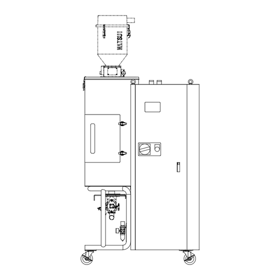
Page 11: Outer Dimensions
W W2 The collection unit on the dry unit (The from differs on the specification) Model W (mm) W2(mm) D (mm) D2 (mm) H (mm) Outline mass (kg) MGD-15J 1472 1149 1258+α MGD-25J 1472 1149 1508+α MGD-50J 1000 1737 1152 1597+α... -
Page 12: Name Of Each Part
Chapter 2 Explanation Equipment 4. Name of each part Inside unit Primary convey suction port Secondary loader suction port Secondary loader suction port MGD-15~150 Primary convey suction port Door side door MGD-200~300 Door Primary convay suction port Primary convay Jet clone material port Convey selection valve Ventilation... -
Page 13: Name And The Function Of Each Controller Part
Chapter 2 Explanation Equipment 5. Name and the function of each controller part Dryer Drying Heater Feeder 1 Value indication 数値 表示 器 Regeneration Heater Feeder 2 unit Feeder 3 Feeder 1 Feeder 2 Feeder 3 Dryer Reset 本文中の説明で はEnterと記 述 ENTER is described in the explanation of this manual. -
Page 14: Wiring Diagram To Level Sensor For The Collective Unit At End Of The Convey
Chapter 2 Explanation Equipment 6. Wiring diagram to level sensor for the collective unit at end of the convey 【ASDレベル計制御配線要領】 【JCリミット制御配線要領】 【JCレベル計制御配線要領】 [Wiring point of JC limit control] [Wiring point of JC level gage control] [Wiring point of ASD level gage control] Limit リミットスイッチ... -
Page 15: Precautions Every Unit Equipment
Chapter 2 Explanation Equipment 7. Precautions every unit equipment The handling explanation (particularly precautions) every unit equipment that is incorporated into this unit is described. Conform and operate the specified precautions for this unit and unit equipment. 【Model name: Push damper】(Type: PD3-φ38(φ50)) 1. - Page 16 Chapter 2 Explanation Equipment 2. Name of each part and removal method for cylinder unit Solenoid valve W A R N I N G ^ 5 WATCH^5 YOUR FINGERS ・You may have your^1 fingers cut off^1 or broken. ・When performing cleanup or inspe- ction,turn off power and shut off...
-
Page 17: Installation For Equipment
Chapter 3 Installation 1.Installation for equipment Step Item Description 1 Installation Install on the levelly stable floor. As shown in figure, make sure the installation location gives space to perform maintenance. 2 Caster brake As shown in figure, apply the brake of the caster with brake. Please do not step on the brakes excessively. - Page 18 Chapter 3 Installation Step Item Description 2 Moving the unit As shown the figure, when lifting and moving this unit, confirm the protest condition of the installation eye bolt in the upper part. Then, hang and move a hoisting rope (with hook) in the lift with the your plant’s crane.
- Page 19 Chapter 3 Installation Item Description 3 Installation of <In case of primary convey> ・Connect the primary side PVC hose and the convey hose port (suction the hopper on nozzle etc.). Fasten up the connection part surely by the hose band. the molding unit <In case of secondary convey>...
-
Page 20: Power Supply Connection
Chapter 3 Installation 2.Power supply connection Step Item Description 1 Connection of Connect to your power breaker with the power code. power cord 3 phase alternating current power R:S:T: Earth CAUTION ・Before connecting a power code, surely make a power breaker OFF. -
Page 21: Preparation For Operation
Chapter 4 Preparation for Operation 1.Inspecting inside of the hopper Step Description 1 Open the checking door after confirming that a resin isn't included inside the dry hopper. Confirm whether or not there is not foreign material inside the hopper. 2... - Page 22 Chapter 4 Preparation for Operation Unit name Confirmation unit and checking item Blower suction port ・Confirm the setting of the filter. ・Confirm the complete is opened of the damper. Damper (Filter inside) CAUTION When operating a damper in the incomplete opening condition, it becomes a cause for overheat (upper limit alarm) with dry temperature from the suction airflow rate lack.
- Page 23 Chapter 4 Preparation for Operation Unit name Confirmation unit and checking item Jet Clone filter Sets a filter surely and confirm whether or not there is not a packing Collection unit on each slip. molding unit 蓋 パッキン Packing フィルタ Filter キャッチクリップ...
-
Page 24: Controller Setting
Chapter 4 Preparation for Operation Unit name Confirmation unit and checking item NOTE Obtain 0.5 MPa minimum for the pressure of dry, compressed air from the compressed air source. Use clean, dry air that was treated with the air dryer and the air filter. In particular, the wastewater must be completely drained to prevent it from being frozen in a cold district. - Page 25 Chapter 4 Preparation for Operation Step Confirmation unit and checking item Start timer Press the SV switch. Press a present setting value alternately until a dLy is displayed on the indicator. Press the Enter switch. The present setting value blinks on the indicator. ...
- Page 26 Chapter 4 Preparation for Operation Step Confirmation unit and checking item No.1 Convey timer Press the SV switch. (In case with primary Press a present setting value alternately until a Fd1 is displayed on convey) the indicator. Press the Enter switch. The present setting value blinks on the indicator.
- Page 27 Chapter 4 Preparation for Operation Step Confirmation unit and checking item NOTE Initializes the convey timer in 25 seconds so as not for the convey blower to be able to start up above 60 times per hour for to protect of the convey blower about MGD-200-300. In under the condition of the conveying distance, the collection unit capacity, etc., the adjustment to make short is necessary when 25 seconds is long.
- Page 28 Chapter 4 Preparation for Operation Step Confirmation unit and checking item MGD-15~150 1.Setting range………………999 sec. 2.Shipment setting value……15sec. 3.Standard setting value In case of the suction box installing without the profile damper….15 sec. In case of the suction box installing with the profile damper….
- Page 29 Chapter 4 Preparation for Operation Step Confirmation unit and checking item No.3 Convey timer Press the SV switch. (In case with two Press a present setting value alternately until a Fd3 is displayed on the indicator. directions of the secondary convey) Press the Enter switch.
- Page 30 Chapter 4 Preparation for Operation Step Confirmation unit and checking item MGD-200~300 1.Setting range………………999 sec. 2.Shipment setting value……25sec. 3.Standard setting value In case of the suction box installing without the profile damper….25 sec. In case of the suction box installing with the profile damper….
- Page 31 Chapter 4 Preparation for Operation Step Confirmation unit and checking item Set to the discharge time that material in the collection unit on the dry unit (Jet clone etc.) is fully discharged. Push the ▲ ▼ switch and change the setting value. When pushing these switches, the value becomes the addition and the subtraction in order.
- Page 32 Chapter 4 Preparation for Operation Step Confirmation unit and checking item 1.Setting range………………999 sec. 2.Shipment setting value……25 sec. 3.Standard setting value…… Hopper on the molding unit without discharge valve…3 sec. Hopper on the molding unit with discharge valve……25 sec. No.3 Discharge timer Press the SV switch.
- Page 33 Chapter 4 Preparation for Operation Step Confirmation unit and checking item No.2 Material Press the SV switch. beginning timer Press a present setting value alternately until a bt2 is displayed on the indicator. (In secondary convey, in case of the suction box under the dry unit is Press the Enter switch.
- Page 34 Chapter 4 Preparation for Operation Step Confirmation unit and checking item No.3 Material Press the SV switch. beginning timer Press a present setting value alternately until a bt3 is displayed on the indicator. (In secondary convey with two directions, in case of the suction Press the Enter switch.
-
Page 35: Setting The Overheat Protector
Chapter 4 Preparation for Operation 4.Setting the overheat protector For safety, this unit has an overheat protector as standard equipment. If the sensor (temperature detector) reaches a temperature higher than the temperature setting of the overheat protection device, the power supplies to the heater is cut off. -
Page 36: Jet Clone Operation Explanation
Chapter 4 Preparation for Operation 5. Jet Clone operation explanation When the start / stop Feeder 1 switch of the line installed Jet clone is “ON”, the discharge timer is working and the blower rotates in the time up. The damper of the collection unit closes at the same time. ↓... -
Page 37: Outline Of Aero Power Hopper
Chapter 4 Preparation for Operation 6. Outline of Aero Power Hopper This is a material conveyance hopper installed onto the molding machine. This has the following features by flowing conveying material in hopper. ① Fine powders and particles are separated and removed. ②... - Page 38 Chapter 4 Preparation for Operation 3. Test run adjustment 1. Sensor sensitivity adjustment (Proximity switch E2K type) If the presence or absence of the material is not correctly detected, adjust the sensitivity of the proximity switch by the following procedure. (1) Remove the material in the hopper.
- Page 39 Chapter 4 Preparation for Operation 2. Adjustment of sensor installing position (Not applicable to APH-1 type) The sensor can be moved up and down by slightly loosening the M5 screws (two pieces) fixing the sensor bracket and plastic bracket. Securely tighten the M5 screws (two pieces) after adjustment. Plastic bracket M5 screw (two pieces) Sensor...
- Page 40 Chapter 4 Preparation for Operation 4. Maintenance and check Cleaning of filter A filter (porous plate made of stainless steel) is provided in the upper hopper. As it is clogged with fragments of crushed material, regularly remove them. Damper A damper is incorporated in the upper hopper discharge part. This damper is suspended by two stainless steel wires of 0.5mm.
- Page 41 Chapter 4 Preparation for Operation 6. Specifications Model APH- Conveying pipe caliper (mm) Suction pipe caliper (mm) Maximum conveying amount (kg) Conveying hopper capacity (L) Conveying hopper diameter (mm) Charge hopper capacity (L) +allowa +allowa (Demand level switch) nce 2 nce 4 Charge hopper...
-
Page 42: Operating Procedures
Chapter 5 Operating Procedures Step Operation Description 1 Power ON Set the power breaker in front to “ON”. 2 Preparations for Press the CONTROL ON switch in the front. operation The display of controller lights up. 3 No.1 Convey When pressing Feeder 1 switch, the indicator in the upper left of Feeder 1 start-up switch lights up and the material convey operation of No.1directions starts. - Page 43 Chapter 5 Operating Procedures Step Operation Description No.1 Convey stop 7 1) Press Feeder 1 switch. If the indicating lamp keeps turned on, it will be switched off when the (In case with primary conveying cycle for No.1 direction finishes. convey) If the indicating lamp is blinking during material conveyance, the blinking will Drying stop...
-
Page 44: Chapter 6 Maintenance
Chapter 6 Maintenance This chapter describes the possible causes of troubles you may encounter and the actions to be taken against them. WARNING Never fail to examine the causes of any trouble and take remedies after allowing the molder to cool for 5 hr after stopping. (Use gloves.) It is very dangerous during and immediately after operations becomes it is very hot. - Page 45 Chapter 6 Maintenance Maintenance item Description Discharge of dust from dust Discharge the dust that has clogged in the dust tube. tube Remove the dust cap on the bottom of the dust tube and discharge the dust. NOTE After discharging, be sure to refasten the dust cap securely. Exhaust filter case Dust tube Dust cap...
-
Page 46: Weekly Maintenance
Chapter 6 Maintenance 2. Weekly maintenance Maintenance item Description Filter cleaning CAUTION 1. Use a mask because the clinging particles of the filter spray the spraying clean of dry air in the air. 2. When a filter is clogged, it does the looseness of operation temperature and airflow rate. - Page 47 Chapter 6 Maintenance Maintenance item Description Exhaust filter of exhaust Remove the catch clips (2) on the bottom of the exhaust filter case and remove the exhaust filter. filter case inside Blow clean dry air inside the exhaust filter and remove clinging particles. Exhaust filter case Catch clip Exhaust filter...
- Page 48 Chapter 6 Maintenance Maintenance item Description Dust hopper for Remove the dust hopper and remove the fine particle that is stagnant inside. air source unit Catch clip Dust hopper ※The degradation of packing be terrible and exchange for the new packing when being transformed, discoloring and becoming solid.
- Page 49 Chapter 6 Maintenance Maintenance item Description Sensitivity adjustment by When the level gage doesn't sense correctly by the kind of material, the sensitivity adjustment is necessary. the paddle type level gage (Using the paddle –type 【Adjusting method】 level gage) Adjust sensitivity at the specific gravity of convey material. ①After turning the lid of the level gage, and remove.
- Page 50 Chapter 6 Maintenance Maintenance item Description When not measuring the full material correctly, adjust the sensitivity of Weigh request gauge the proximity switch by the following procedure. (Proximity switch) Sensitivity adjustment (1) Remove material in the glass tube. method (2) Confirm there is no between the end of proximity switch and glass tube. If th is a gap between them, loosen fastening screws (2pcs.) of proximity switch fitting bracket and fix proximity switch with its end touching glass tube.
- Page 51 Chapter 6 Maintenance Maintenance item Description Adjustment for the Jet When the damper doesn't open until the full signal appears on, adjust a リミットスイッチ Clone damper cam in Limit switch damper cam by following procedure. upper part of the dry hopper ダンパー...
-
Page 52: Monthly Maintenance
Chapter 6 Maintenance 3. Monthly maintenance Maintenance item Description Rising fastens for Confirm the loosening of the wiring connection part of the electronics equipment inside the control panel and in the unit. And, perform the rising the terminal fastens in the connection part. CAUTION The check is after stop the unit, always perform after turned “OFF”... -
Page 53: Every Six Months Maintenance
Chapter 6 Maintenance Maintenance item Description Check for each jet clone part Upper stopper adjustment position Limit switch ON position Lower stopper adjustment position (Clearance gap 6mm) Stopper adjustment figure 4. Every six months maintenance Maintenance item Description Bolt and Nat Check about whether there is not loosening of bolt and Nat at each part of the unit. -
Page 54: Every Year Maintenance
Chapter 6 Maintenance 5. Maintenance performed every year Maintenance item Description Controller Replace the drying heater output relay. main circuit board 1.Turn OFF the operation “ON/OFF” switch of the device, and open the control panel of the device after turning “OFF” the power breaker on the right side of the control panel. -
Page 55: Chapter 7 Alarms Function
Chapter 7 Alarms Function CAUTION Before doing the check of the malfunction cause and recovery, always perform the power breaker of control panel “OFF”. The work with power “ON”, causes the trouble and the accident. Don't do absolutely. When the malfunction occurs during operation of the equipment, the protection unit operates, the alarm character is displayed in the control panel and the alarm buzzer sounds and informs the malfunction. - Page 56 Chapter 7 Alarm Function Alarm Character Malfunction contents/Interlock Measure indicator indicator Dry sensor When wiring for the thermocouple Refer to CHAPTER 8. Troubleshooting (AC sensor) and the thermocouple Malfunction and restore extraordinary occurrence cause. for the dryness are broken. ↓ When pushing a Reset switch after The operation stops automatically.
-
Page 57: Chapter 8 Troubleshooting
Chapter 8 Troubleshooting This chapter describes the possible causes of troubles you may encounter and the actions to be taken against them. Check the following troubleshooting table before requesting our service. When a problem cannot be solved even after taking the actions described here, contact the nearest our service division. - Page 58 Chapter 8 Troubleshooting The Convey blower does not rotate. Check point Remedy Note Confirm whether or not the limit switch At the time of "ON", refer to the When a right adjustment isn't of jet clone at the end of convey doesn't full signal adjustment of jet performed, the convey stop become “ON”...
- Page 59 Chapter 8 Troubleshooting The blower does overloaded operation and the thermal relay trips. Check point Remedy Note Remove the cartridge filter in the When there are dirt and stuff, blow When the degradation of cartridge filter case of the convey line and the clean dry air into the cartridge filter progresses and it isn't possible check the filter stuff.
- Page 60 Chapter 8 Troubleshooting A little air flow rate of the blower. Check point Remedy Note When operating in the closed Confirm whether or not the damper Full opens a damper. condition, in the insufficiency in the for airflow adjustment of the dry suction airflow, the overheat (upper blower is open.
- Page 61 Chapter 8 Troubleshooting The dry temperature doesn't up and down. Check point Remedy Note Check that the dry heater is broken. When a heater is broken, exchange a After the unit stops, making a power breaker “OFF”, and work heater. after downed with the range of the heating part temperature that doesn't get burned.
- Page 62 Chapter 8 Troubleshooting The upper limit alarm with dry temperature occurs. Check point Remedy Note Remove the filter in the dry blower When there are dirt and stuff, blow When the degradation of filter and check the filter stuff. the clean dry air into the filter and progresses and it isn't possible to remove clinging particles, exchange remove the clinging particles.
-
Page 63: Chapter 9 Technical Manual
Chapter 9 Technical Manual 1. The shipment setting value for the controller The parameter for the user setting mode Of pushing SV switch every, the parameter indicator switches over. But when pushing SV switch more than 5 seconds, changes to the engineering setting mode. Be careful. Initial Character Setting range... -
Page 64: The Start-Up Method For The Auto Tuning
Chapter 9 Technical Manual 2. The start-up method for the auto tuning ① During the dry unit operating, starts the auto tuning when push continuing △ and ▽ key at the same time for 2 seconds during display of the dry temperature measurement value. (During auto tuning, displays alternately at the period in 1 second in the measurement temperature and「At」) ②... - Page 65 Chapter 9 Technical Manual ○The resin list which needs the unit measure that the influence of gas is estimated The resin that gas compatible column in the table had ○ mark needs compatible. × mark is unnecessary but depending on kind of the compounding material, it has possibility that the compatible becomes necessary.
-
Page 66: The Relation Between Dew Point And Dryness Under The Fresh Air Condition
Chapter 9 Technical Manual 4. The relation between dew point and dryness under the fresh air condition The dry air dew point changes in the fresh air-condition (dew point and humidity). Be careful because doesn't down to fix moisture content when the dry air dew point becomes wrong. The following graph shows the change of dry air dew point and dry curve in under our dry unit. -
Page 67: Chapter 10 Consumable Parts List
1. The recommended replacement cycle is use environment, it will vary depending on usage. 2. Item 8, 9 if that is the exchange of over-temperature prevention instrument, will be the safety device parts always nearest because Please contact the Corporation Matsui SDI (back cover). - 63 -... - Page 68 1. The recommended replacement cycle is use environment, it will vary depending on usage. 2. Item 8, 9 if that is the exchange of over-temperature prevention instrument, will be the safety device parts always nearest because Please contact the Corporation Matsui SDI (back cover). - 64 -...
- Page 69 1. The recommended replacement cycle is use environment, it will vary depending on usage. 2. Item 8, 9 if that is the exchange of over-temperature prevention instrument, will be the safety device parts always nearest because Please contact the Corporation Matsui SDI (back cover). - 65 -...
- Page 70 1. The recommended replacement cycle is use environment, it will vary depending on usage. 2. Item 8, 9 if that is the exchange of over-temperature prevention instrument, will be the safety device parts always nearest because Please contact the Corporation Matsui SDI (back cover). - 66 -...
- Page 71 1. The recommended replacement cycle is use environment, it will vary depending on usage. 2. Item 8, 9 if that is the exchange of over-temperature prevention instrument, will be the safety device parts always nearest because Please contact the Corporation Matsui SDI (back cover). - 67 -...
- Page 72 1. The recommended replacement cycle is use environment, it will vary depending on usage. 2. Item 8, 9 if that is the exchange of over-temperature prevention instrument, will be the safety device parts always nearest because Please contact the Corporation Matsui SDI (back cover). - 68 -...
- Page 73 1. The recommended replacement cycle is use environment, it will vary depending on usage. 2. Item 8, 9 if that is the exchange of over-temperature prevention instrument, will be the safety device parts always nearest because Please contact the Corporation Matsui SDI (back cover). - 69 -...
- Page 74 1. The recommended replacement cycle is use environment, it will vary depending on usage. 2. Item 8, 9 if that is the exchange of over-temperature prevention instrument, will be the safety device parts always nearest because Please contact the Corporation Matsui SDI (back cover). - 70 -...
- Page 75 1. The recommended replacement cycle is use environment, it will vary depending on usage. 2. Item 8, 9 if that is the exchange of over-temperature prevention instrument, will be the safety device parts always nearest because Please contact the Corporation Matsui SDI (back cover). - 71 -...
-
Page 76: Chapter 11 Options
Chapter 11 Options 1. The short circuit breaker Install a short circuit breaker on the power breaker. Then, protect earth fault, overload, and short circuit and prevent from a short circuit. Symbol Name Maker Model ELB-1 Short circuit breaker Mitsubishi Electric. Refer to chapter 12 "Change part list by using voltage". -
Page 77: The Extension Starting Stop
Chapter 11 Options 3. The extension starting stop Performed to do this dryer in "Operation-Stop" by the extension signal. (The extension start signal prepare A breaker points of voltageless) The extension start signal connects a signal line to the terminal board in the control panel. The extension start signal starts in "ON"... -
Page 78: The Alarm Indicator
Chapter 11 Options 5. The alarm indicator 1) Revolving light Possible to confirm in the wide range by lighting up at all alarms operating. 警報表示 器 Alarm indicator GENERAL ALARM IND. General alarm indication 総合警報表 示 REVOLVING LIGHT Revolving light PTL-1 回... -
Page 79: Difference Voltage Compatible
Chapter 11 Options 6. Difference voltage compatible This dryer can do compatible with difference voltage in the option. (You consult, being special about compatible in orders and the remodeling of the delivery number). 7. The operating power 100V This dryer can correspond to 100 V of operating powers with the option. *5:CONTROL CIRCUIT AC100V *5: Control circuit AC 100V *5:操作回路AC100V... -
Page 80: Connecting For Jet Selector
MGD main unit (rear) In ( ) is in case of installation in secondary convey side. Name Maker Model Q’ty 1 1 Ball of installing JSV Matsui For installing JSV W-38×1~2m (MGD-15~150) 2 1 PVC hose Tigers Polymer W-50×1~2m (MGD-200~300) AK-1045 2... - Page 81 Chapter 11 Options Install JSV to the secondary convey side and in case of performed the specification with the profile damper (Push damper) to the suction box, performs the timer setting in according to the following point (Time chart) 要求 Request 輸送先要求レベル計...
-
Page 82: The Secondary Convey: 2 Directions
Name Maker Model Q’ty 2 direction branch unit φ38×L700×2-direction (MGD-15~150) 1unit Install in case of the suction box is 1 Matsui Mfg. specification with the profile damper 1unit 40×L900×2-direction (MGD-200~300) (Push damper). 1 3VN-φ38(MGD-15~150) 2 3 direction select valve Matsui Mfg. -
Page 83: 10.Lower Limit Level Alarm Switch
10.Lower limit level alarm switch With lower limit level alarm switch to be installing in the hopper, we report material low level. Use with the option of alarm indicator light(Rotating lamp、Laminating lamp). Referential remnant MGD-15J 7.5 L MGD-25J MGD-50J 16 L... -
Page 84: Chapter 12 Specifications
Chapter 12 Specifications Equipment model 100J 150J 200J 250J 300J liter kg/BD:0.6 kg/BD:0.8 hopper Thermal Glass wool heat cut + Exterior board ~130 Standard ℃ Dry temp. ~160 High temp. NK-5 Model RS-205 RS-301 RS-302N NB-5 blower Motor output W 28/34 130/200 135/195...
Need help?
Do you have a question about the MGD-15J and is the answer not in the manual?
Questions and answers