Advertisement
Quick Links
About this Manual
This manual is included as a quick reference for installation. For
further information on the use of this device with an FACU, please
refer to the panel's manual.
Note: This manual should be left with the owner/operator of this
equipment.
This manual covers the following models:
FHS-400-LF-WW White wall mounted low frequency sounder/
strobe
FHS-400-LF-RR Red wall mounted low frequency sounder/strobe
Notes
• DO NOT PAINT OR ALTER FACTORY APPLIED FINISH IN
ANY WAY.
• NE PAS PEINDRE OU MODIFIER LA FINITION
ORIGINALE.
• Use the information in this document to determine the total
current draw of the devices. The total current draw of the
devices must not exceed the power supply of the panel. In all
cases, the installer should consider the voltage drop to
ensure that the last device on the circuit operates within its
rated voltage.
• Wiring must be in accordance with CSA C22.1 Section 32
Description
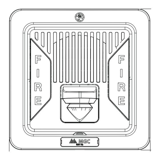
The low frequency 400 series sounder/strobe provides a wide
range of low frequency audible and visual settings in a single
compact device. These low frequency devices operate within a
range of 520 Hz ± 10% which address the NFPA 72 sleeping
space requirements. The low frequency sounder/strobe can be
synchronized using an FACU or PSU with the MGC protocol or
through an external sync module for compatibility with any UL/
ULC listed FACU or PSU.
Sounder/strobe models are approved for wall installations.
Specifications
Operating temperature:
Humidity range:
Strobe flash rate:
Nominal Voltage:
Operating Voltage Range
(RMS):
Frequency Range:
Input terminal wire gauge:
Installation environment:
Warranty
Purchase of all MGC products is governed by:
https://www.mircom.com/product-warranty
https://www.mircom.com/purchase-terms-and-conditions
https://www.mircom.com/software-license-terms-and-conditions
1
Notification Appliances - Sounder/Strobe
0°C to 50°C (32°F to 122°F)
0% to 93%
1 Hz
Regulated 24 VDC / 24 VFWR
16 - 33 VDC / VFWR
520 Hz ± 10%
22 AWG to 12 AWG
For indoor use only
Low Frequency 400 Series
Setting the DIP Switches
DIP switch 1
DIP switch 6
NOTE for switch 1: Use NON-SYNCHRONIZED when the
appliances do not need to be synchronized. Use
SYNCHRONIZED when synchronization is required, either
through a sync module or built-in synchronization on the
control unit.
When SYNCHRONIZED is selected, the settings for switches
3, 4 and 5 are ignored.
When NON-SYNCHRONIZED is selected, the sounder will
sound only the audible pattern as selected through switches
3, 4 and 5.
Switch 2 is not used. By default it is OFF.
Input
NON-SYNCHRONIZED
SYNCHRONIZED
Signal Rate
DIP Switch 3
Continuous
OFF
March Time
OFF
Temporal 3
OFF (default)
Temporal 4
ON
20 BPM
OFF
Sounder Volume
High
Normal
Setting the Candela
The candela can be set to 15, 30, 75, 15/75,110 and 185. The
factory default setting is 15.
1.
Pull out the plastic selector tab from the back of the device.
2.
Re-insert the selector tab into the notch that is labeled with
the desired candela setting.
When removing or inserting the candela selector, ensure to
keep it straight.
Note: Select the candela setting before installing the device in the
mounting plate.
www.mircomgroup.com LT-6787 Rev. 0 July 2024
DIP Switch 1
ON
OFF (default)
DIP Switch 4
DIP Switch 5
OFF
OFF
ON
OFF
ON (default)
ON (default)
OFF
OFF
OFF
ON
DIP Switch 6
ON
OFF (default)
Advertisement

Related Manuals for MGC 400 Series

Summary of Contents for MGC 400 Series
- Page 1 520 Hz ± 10% which address the NFPA 72 sleeping 20 BPM space requirements. The low frequency sounder/strobe can be synchronized using an FACU or PSU with the MGC protocol or Sounder Volume DIP Switch 6 through an external sync module for compatibility with any UL/ High ULC listed FACU or PSU.
- Page 2 CAN/ULC S524 and NFPA 72. mounting plate to gang box Cover Mount the unit with the MGC logo at the bottom. The appliance is compatible with double gang or 4” square boxes. Before mounting, disassemble the unit as shown on the right.
- Page 3 Operating RMS Currents (mA) Sounder/Strobe Operating RMS Currents (mA) 16 VDC - 33 VDC 16 VFWR - 33 VFWR Coded Tone* Continuous Tone Coded Tone* Continuous Tone Candela Normal Volume High Volume Normal Volume High Volume Normal Volume High Volume Normal Volume High Volume 15/75...
Need help?
Do you have a question about the 400 Series and is the answer not in the manual?
Questions and answers