Advertisement
Advertisement
Table of Contents

Subscribe to Our Youtube Channel
Related Manuals for Summit Racing SUM-900646


Summary of Contents for Summit Racing SUM-900646
-
Page 2: Table Of Contents
Table of contents Safety ............2 Maintenance ..........15 Specifications ..........6 Parts List and Diagram ......18 Setup ............7 Warranty ............ 20 Operation ........... 12 WARNING SyMBOLS AND DEFINITIONS This is the safety alert symbol. It is used to alert you to potential personal injury hazards. - Page 3 personal Safety 1. Stay alert. Watch what you are doing and Use safety equipment. use common sense when operating the tool. A dust mask, non-skid safety shoes Do not use the tool while tired or under the and a hard hat must be used for the influence of drugs, alcohol, or medication.
- Page 4 Air Source Never connect to an air source that 2. Never use oxygen, carbon dioxide, combustible is capable of exceeding 200 psi. gases or any bottled gas as an air source Over pressurizing the tool may cause for the tool. Such gases are capable of bursting, abnormal operation, explosion and serious injury to persons.
- Page 5 6. Obey the manual for the air compressor 8. Use this tool with both hands only. Using tools used to power this tool. with only one hand can result in loss of control. 7. Install an in-line shutoff valve to allow 9.
-
Page 6: Safety
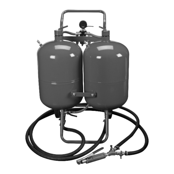
Functional Description Specifications Maximum Air Pressure 125 PSI Air Inlet 1/4"–18 NPT Required Air Hose 3/8" 6 CFM @ 60 PSI Average Air Consumption 25 CFM @ 125 PSI Abrasive Capacity 100 lb per Tank components and controls Filler cap Safety Valve Filler cap... - Page 7 Initial Tool Set Up/Assembly Read the ENTIRE IMpORTANT SAFETy INFORMATION section at the beginning of this manual including all text under subheadings therein before set up or use of this product. Note: For additional information regarding the parts listed in the following pages, refer to the Assembly Diagram near the end of this manual.
- Page 8 Assembly (continued) Water Trap Filter (17) Air pressure Gauge (16) 6. Wrap the threads of the Air Pressure Gauge (16) with thread sealer tape. Screw the Gauge into the Inlet Manifold (15) threaded opening on top of the Inlet Manifold (15) and tighten.
-
Page 9: Operation
Air Supply TO pREVENT SERIOUS INJURy FROM EXpLOSION: Use only clean, dry, regulated, compressed air to power this Blaster. Do not use oxygen, carbon dioxide, combustible gases, or any other bottled gas as a power source for this Blaster. 1. Incorporate a filter, regulator with pressure gauge, 3. - Page 10 Page 10...
- Page 11 Page 11...
- Page 12 Operating Instructions Read the ENTIRE IMpORTANT SAFETy INFORMATION section at the beginning of this manual including all text under subheadings therein before set up or use of this product. Inspect tool before use, looking for damaged, loose, and missing parts. If any problems are found, do not use tool until repaired.
- Page 13 2. close the Air Supply Valve, Red and c. Squeeze the Trigger Valve to Green Abrasive Valves, purge Valve, release the abrasive. and Red and Green Throttle Valves, then Note: The flow rate of the abrasive may connect and turn on the air supply. be irregular when the unit is first started.
- Page 14 General Operating Instructions (continued) 9. Move the Blast Gun in a circular or right 14. If sodium bicarbonate blast media was used, to left motion until the desired finish on any blast media left in the Soda Tank MUST be the workpiece has been achieved.
-
Page 15: Maintenance
User-Maintenance Instructions procedures not specifically explained in this manual must be performed only by a qualified technician. TO pREVENT SERIOUS INJURy FROM AccIDENTAL OpERATION: close all Valves, detach the air supply, safely discharge any residual air pressure in the tool, and close all Valves again before performing any procedure in this section. TO pREVENT SERIOUS INJURy FROM TOOL FAILURE: Do not use damaged equipment. - Page 16 User-Maintenance Instructions (continued) Nozzle Replacement To change Blast Gun Nozzle size to suit the Blast Gun blast media being used or to replace a worn Nozzle, use the following procedure: Nozzle Nozzle cap Nut a. Unscrew and remove the Nozzle Cap Nut. b.
- Page 17 pLEASE READ THE FOLLOWING cAREFULLy THE MANUFACTURER AND/OR DISTRIBUTOR HAS PROVIDED THE PARTS LIST AND ASSEMBLY DIAGRAM IN THIS MANUAL AS A REFERENCE TOOL ONLY. NEITHER THE MANUFACTURER OR DISTRIBUTOR MAKES ANY REPRESENTATION OR WARRANTY OF ANY KIND TO THE BUYER THAT HE OR SHE IS QUALIFIED TO MAKE ANY REPAIRS TO THE PRODUCT, OR THAT HE OR SHE IS QUALIFIED TO REPLACE ANY PARTS OF THE PRODUCT.
-
Page 18: Parts List And Diagram
parts List and Diagram parts List part Description part Description Soda Tank Air Supply Valve 3/8" Abrasive Tank Red Throttle Valve 3/8" Wheel Green Throttle Valve 3/8" Cotter Pin Air Hose Front Leg Abrasive Outlet Manifold Axle / F rame Assembly Hose Clamp Handle Abrasive Hose... - Page 19 Assembly Diagram Page 19...
Need help?
Do you have a question about the Racing SUM-900646 and is the answer not in the manual?
Questions and answers