
Related Manuals for AW-Lake TA3

Summary of Contents for AW-Lake TA3
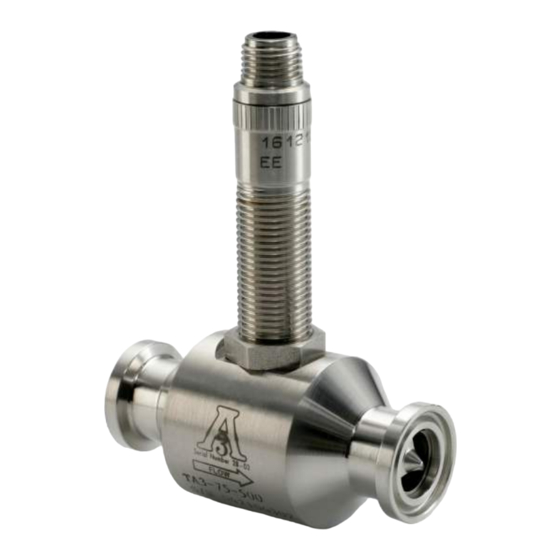
- Page 1 C O M PA N Y Sanitary Turbine Flow Meter - TA3 Installation, Operating & Maintenance Manual ©2016 AW-Lake Company. All rights reserved. Doc ID:SANITARYMAN16...
-
Page 2: Mechanical Specifications
Mechanical Specifications Maximum Operating Pressure Measuring Accuracy ± 1.0% of reading or better Working pressure up to 1,000 psi Repeatability Temperature Range Fluid temperature up to 300°F ± 0.1% Electrical Connection Flow Measuring Range 0.6 to 400 GPM (gal/min) NEMA 6 Connector Turn Down Ratio Port Connection Tri-clamp... - Page 3 Meter Specifications Part Range K-Factor * Meter Clamp Size Weight Number (gal/min) (Pulses/ gal) Size (lbs) TA3-75-375 0.6 to 3 20,000 3/8” 3/4” TA3-75-500 0.75 to 7.5 13,000 1/2” 3/4” TA3-75-750 2 to 15 2,750 1/2” 3/4” TA3-150-500 0.75 to 7.5 13,000 1/2”...
-
Page 4: Theory Of Operation
Introduction The TA-3 Sanitary turbine flow meter is designed with wear resistant moving parts to provide trouble-free operation and long service life. The durable 316L stainless steel construction provides a cost efficient flow measurement system that offers excellent accuracy and repeatability. The TA-3 Sanitary turbine meter repair kit is designed for easy field service of a damaged flow meter, rather than replacing the entire flow meter. -
Page 5: Installation
Installation WARNING: The meter should not be subjected to temperatures above 300° F (149° C), below -150° F (-101°C) or the freezing point of the metered liquid. High temperatures will damage the magnetic pickup, while lower temperatures will limit the rotation of the rotor. WARNING: Incompatible fluids could deteriorte internal parts and cause the meter to read inaccurately. - Page 6 Severe pulsation and mechanical vibration affects accuracy and shortens the life of the meter. The preferred plumbing setup is one containing a bypass line that allows meter inspection and repair without interrupting flow. See Figure 2. If a bypass line is not utilized, it is important that all control valves be located downstream of the flow meter.
- Page 7 Do not locate the flow meter or connection cable close to electric motors, transformers, sparking devices, high voltage lines, or place connecting cable in conduit with wires furnishing power for such devices. These devices can induce false signals in the flow meter coil or cable causing the meter to read inaccurately.
-
Page 8: Dimensions And Drawings
Dimensions and Drawings Figure 5: Dimensions Table 4: Dimensions Part Number TA3-75-375 3.00 in. (76 mm) 1.5 in. (38 mm) 1 in. (25 mm) TA3-75-500 3.00 in. (76 mm) 1.5 in. (38 mm) 1 in. (25 mm) TA3-75-750 3.00 in. (76 mm) 1.5 in. - Page 9 Repair Kit Fits Meter Repair Kit Part Bore Size Ferrule Size Part Number Number 3/8 in. (9.53 mm) 1 in. (25 mm) TA3-75-375 TA3-375 1/2 in. (12.7 mm) 1 in. (25 mm) TA3-75-500 TA3-500 3/4 in. (19.05 mm) 1 in. (25 mm)
- Page 10 3-A Turbine Disassembly and Cleaning Procedure WARNING: High-pressure leaks are dangerous and cause personal injury. Make sure that fluid flow had been shut off and pressure in the line released before attempting to remove the meter. NOTE: Refer to Figure 7 for relative positions of repair kit components. 1.
- Page 11 Figure 7: TA-3 Sanitary Turbine Exploded View Meter Body Sleeve Bearing Jam Nut Rotor Support Magnetic Pickup Retaining Ring SECTION A-A Thrust Ball Rotor Assembly Release Jam Nut and Remove Magnetic Pickup Remove Rotor Supports Do Not Rotate During Extraction Remove Rotor Remove Retaining Rings Thrust Ball Extraction Hole...
- Page 12 NOTE: After installing the new repair kit, the electronics will need re-calibration. Refer to the electronics’ installation and operation manual. If there are any questions on re-calibration, contact AW-Lake Company at 1.800.850.6110 or contact the manufacturer of the associated electronics.
-
Page 13: Troubleshooting Guide
Troubleshooting Guide... - Page 16 C O M PA N Y 262.884.9800 | www.aw-lake.com 2440 W. Corporate Preserve Dr. #600 Oak Creek, WI 53154 ©2016 AW-Lake Company. All rights reserved. Doc ID:SANITARYMAN16...
Need help?
Do you have a question about the TA3 and is the answer not in the manual?
Questions and answers