Summary of Contents for AW-Lake WIN
- Page 1 WIN Water Inline Ultrasonic Flow Meter - No Display Installation & Operating Manual ©2021 AW-Lake Company. All rights reserved. Doc ID: WINBMAN091521...
- Page 2 AW-Lake assumes no responsibili�es for this product except as stated in the warranty. • If the customer or any third party is harmed by the use of this product, AW-Lake assumes no responsibility for any such harm owing to any defects in the product which were not predictable, or for any indirect damages.
-
Page 3: Table Of Contents
TABLE OF CONTENTS INTRODUCTION ........................5 PURPOSE OF THIS GUIDE ....................5 TYPICAL WIN FLOW METER ..................5 STANDARD FEATURES AND SPECIFICATIONS..............5 WORKING ENVIRONMENT .................... 7 SERIAL NUMBER ......................7 UNPACKING ..........................7 CHECKING THAT YOU HAVE RECEIVED EVERYTHING ............ 7 INSTALLATION ........................... - Page 4 This page inten�onally left blank. Page 4...
-
Page 5: Introduction
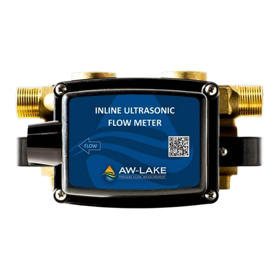
Installa�on Layout WIN Water Inline Ultrasonic Flow Sensor TYPICAL WIN FLOW METER The WIN Inline Flow Meter u�lizes direct path wetted ultrasonic transducers for measuring the volumetric flow of liquids in a wide variety of applica�ons. Output signal(s) • Flush piping system thoroughly before installing meter... - Page 6 GENERAL SPECIFICATIONS PULSE OUTPUT and ANALOG OUTPUT ACCURACY Analog output: 4-20 mA (non-isolated) FLOW ± 1% of reading over 25:1 turndown Scalable pulse output: ± 2% of reading over 100:1 turndown Isolated solid state dry contact Repeatability: ≤ ± 0.2% Contact ra�ng: 50 mA, 30V dc Contact dura�on: 1000ms OVERALL FLOW RANGE...
-
Page 7: Working Environment
SERIAL NUMBER Serial Number The serial number of your WIN is located on the side of the enclosure. The serial number is a unique iden�fier for the product. Please have this number available when contac�ng AW-Lake for assistance. SECTION 2.0: UNPACKING The WIN is generally shipped in one package unless op�onal hardware or equipment is ordered. -
Page 8: Installation
SECTION 3.0: INSTALLATION The WIN Flow Meter should be installed by experienced plumbers, electricians, and others with related knowledge and experience in the hea�ng, cooling, and fluid metering fields. AW-Lake technical support personnel are available via telephone or e-mail to provide technical assistance before, during and after installa�on. -
Page 9: Installing The Flow Meter
Upstream straight unobstructed pipe requirements vary considerably based on the nature of the upstream obstruc�ons. As a general rule, AW-Lake recommends a minimum of 10 diameters of straight unobstructed pipe whenever possible; keeping in mind that it is always recommended that the meter be located with as much straight pipe upstream as possible. - Page 10 The sensor port is always on the Flow Direc�on downstream end of meter. Min. Min. Turn Past Degrees of Model Meter Size Compression Initial Contact Rotation ½” WIN-1S-1N 180° ¾” WIN-1L-2N 120° ¾” WIN-1S-2N 120° 1” WIN-1L-3N 140° 1” WIN-1S-3N 140°...
- Page 11 Orient the meter as shown below. The meter may be installed with upward or downward flow in ver�cal pipes in closed loop pressurized systems. Avoid any installa�on loca�ons where the pipe may not be completely full. Meter Sizes ½ - 1” Preferred Orientation for Horizontal Pipes Do not orient meter as shown below Side View...
- Page 12 Preferred Orientation for Horizontal Housing The sensor port is always on the downstream end of meter. Side View Flow Direc�on Do not orient meter as shown below Page 12...
-
Page 13: Power & Signal Wiring Connections
3.3 POWER AND SIGNAL WIRING CONNECTIONS The WIN is provided with an unterminated 10 foot PVC jacketed cable for power and signal connec�ons. Do not attempt to remove this cable. Doing so will damage the weather-�ght seal and may void the product warranty. Use AWG 18 - 22 shielded cable for power and signal connec�ons.


Need help?
Do you have a question about the WIN and is the answer not in the manual?
Questions and answers