
Related Manuals for LEVTECH LSP-FMS


Summary of Contents for LEVTECH LSP-FMS
- Page 1 Installation and User Instructions Fuel Management System LSP-FMS FMS-24/06-3.0-1.0 EN...
- Page 2 Neither Levtech nor any of its affiliates or subsidiaries shall be responsible or liable for misuse of the information that is contained herein. If you have any suggestions for improvements or amendments or have found errors in this publication, please notify us.
- Page 3 General Notice: Some product names used in this manual are used for identification purposes only and may be trademarks of their respective companies. Product Modifications Year Type Modifications 2024 First model Document Revisions Date Version Number Document Changes 24-06-2024 Initial draft...
-
Page 4: Table Of Contents
Table of Contents Preface ..............................8 Description of the user........................8 Conventions Used in This Manual ....................8 Explanation of Safety Warnings ....................9 Obtaining Documentation and Information .................. 9 1.4.1 Internet ..........................9 1.4.2 Other languages ........................9 1.4.3 Support and service ...................... - Page 5 2.9.4 Fleets ........................... 25 2.9.5 Stock Operations ......................... 25 2.9.6 Database Management ....................... 25 2.9.7 Transactions ........................26 2.9.8 Summarized transactions ....................26 2.9.9 Average Consumption – Period / Detailed ................27 2.9.10 Forecourt ..........................27 2.9.11 TLG Readings ........................27 2.9.12 User Management ......................
- Page 6 4.1.2 Modify an existing vehicle’s data ..................36 Driver operations ........................36 4.2.1 Add a new driver ......................... 36 4.2.2 Modify an existing driver’s data ..................37 Card operations ........................... 37 4.3.1 Add a new card........................37 4.3.2 Modify an existing card ....................... 38 4.3.3 Add a PIN password to a card .....................
- Page 7 5.3.2 Minimum space needed ..................... 44 5.3.3 Conditions for assembling ....................44 5.3.4 Istallation of LSP-FMS ......................44 5.3.5 Electrical installation ......................44 How to Commission the Product ....................45 Operation ............................46 How to use the product ......................46 6.1.1...
-
Page 8: Preface
1 Preface 1.1 Description of the user Only technicians who are familiar with the technical terms, warnings, and instructions in the manual and who are able to follow these should connect the device. Use this device only in accordance with this instruction manual, as well as all applicable local and national laws and regulations. -
Page 9: Explanation Of Safety Warnings
1.4 Obtaining Documentation and Information 1.4.1 Internet The latest version of the documentation is available at the following address: • https://levtech.ro/product/fuel-management-system/ 1.4.2 Other languages This is the English user manual. Manuals in other languages are available upon request. 1.4.3 Support and service... -
Page 10: General Informations
LSP-FMS 2.2 Short Description The LSP-FMS fuel management system is designed to optimize the monitoring, control, and management of fuel usage. This systems is essential for organizations managing large fleets of vehicles, industrial machinery, aircraft, or marine vessels, aiming to improve efficiency, reduce costs, and enhance security. -
Page 11: Technical Data
Low tank level alerting via email • Different user levels • Two card system • Export in .CSV 2.4 Technical Data Product Levtech Fuel Management System Model LSP-FMS Dimensions W:257 x H:219 x L:124 (without cable glands) Weight 1500g, without cables Protection class IP65 Working temperature range -20...+60°C... -
Page 12: Pump Protocols
Relative air humidity 0 - 90%, no condesation Power consumption Max 7W Supply voltage* 230VAC (100-270VAC) / 24VDC Connectors 0.2...2.5mm2 (28AWG...12AWG) Housing material Display size Keypad Capacitive touch Table 1 Technical data table *to be decided when ordering 2.5 Pump protocols Manufacturer Calculator Protocol... -
Page 13: Product Elements
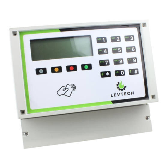
2.7 Product elements Screen Numerical touch buttons Function touch buttons Card reader sensing area Connectors 1 2 3 1 2 3 4 5 6 1 2 3 4 1 2 3 4 1 2 3 4 1 2 3 1 2 3 Power Nozzle Pulser... -
Page 14: Function Touch Buttons
2.7.2 Function touch buttons These four touch buttons are responsible for navigating through the menu. Their function changes depending on which screen is currently displayed. Their function is shown at the bottom of the display above the buttons. Button Text on the LCD Description Turns on the access point BACK... -
Page 15: Numerical Touch Buttons
Figure 4 RFID Tag Figure 3 RFID Cards 2.7.4 Numerical touch buttons These touch buttons allow the user to enter the desired data into the terminal. All the buttons have a beep sound feedback when pushed. The sound feedback cannot be turned off. 2.7.5 Connectors The LSP-FMT terminal is equipped with connectors that can be simply pushed in with a screwdriver or a pointed object to easily connect or disconnect wires. - Page 16 Figure 6 How the connectors work 2.7.5.1 Power connector This connector ensures the power for the terminal. This power can be the mains AC voltage or low DC voltage. Number from Figure 1 PCB silk screen label Meaning L (+U*) Live wire (Positive wire) N (-U*) Neutral wire (Nagtive wire)
- Page 17 2.7.5.3 Pulser IN connector Number from Figure 1 PCB silk screen label Meaning +U Max 62 mA Supply voltage + terminal CH_A Channel A signal CH_B Channel B signal Supply voltage ground Table 6 Pulser IN connector pinout Multiple voltage level generators can be connected to the pulse input. Depending on the pulser, these can be: •...
-
Page 18: Sound Signals
When cabling, it is important to use cable glands. This will ensure the weather resistance of the product. 2.8 Terminal menu You can navigate the LSP-FMS Terminal menu by pressing the capacitive touch buttons and using the display feedback. There are actually two menu branches: the main home screen and the service menu. -
Page 19: Service Menu
2.8.1.1 Single-sided main menu Figure 7 Single-sided terminal main screen You can present your RFID card anytime when this screen is on. After touch, authorize and refuel. 2.8.1.2 Double-sided main menu Figure 8 Double-sided terminal main screen For fuelling, you must first select the pump 1 or pump 2. After the selection, you can present your RFID card/tag. - Page 20 2.8.2.1 1-Display RFID PAN This submenu is used to read the PAN number of RFID cards/members. Once entered, the card can be presented and its number will be immediately written ont he screen. This is not only displayed by the Teminal, but also stored in its internal memory, where it remains until you exit the menu and perform another read.
-
Page 21: Web Interface For Users
Figure 12 System info screens 2.8.2.4 Contrast & Touch Under this menu, you can modify the contrast of the device's display and the sensitivity of the touch buttons. Click on number 1 to get into the Contrast menu to modify the contrast, on number 2 to reach the Touch menu to modify the sensitivity of the buttons. - Page 22 of access, ensuring that only the right people can access different settings. Some configuration options are protected by passwords over different levels of users to prevent unauthorised access, increasing the security of your system. The main menu is accessible from all submenus by clicking on the home screen button. Navigation buttons Home screen...
-
Page 23: Vehicles
Main page Administration Settings Reports User Vehicles Transactions Management Summarized Fuel Settings Drivers Transactions Tank Settings Average Cards Consumption - Detailed Station Fleets Settings Average Lan and Time Consumption Stock Settings Operations - Period Printer Database Forecourt Settings Management Pump TLG Readings Settings TLG Settings... -
Page 24: Drivers
2.9.2 Drivers Figure 17 Drivers page Here is the list of drivers added. You can add new vehicles or change existing ones. 2.9.3 Cards Figure 18 Cards page Here you can add new vehicle or driver cards/tags to the terminal. But you can also modify existing ones. Users have the option to use multiple card systems with the terminal. -
Page 25: Fleets
2.9.4 Fleets Figure 19 Fleets page You can add a new fleet to which you can assign vehicles and drivers. For example, this is how you can group your vehicles. 2.9.5 Stock Operations Figure 20 Stock Operations page This shows the fuel level changes that occur in the tanks. It is also here that any new fuel receipts can be adjusted, or the existing quantity corrected in the event of a shortage or surplus. -
Page 26: Transactions
Don’t initialize a database archiving during a refueling. Depending on how much data gatherd, it can take some time. Don’t cut off the power of the device. During saving, on the LCD appears „OUT OF ORDER”. *the database management is under development to automatize archiving 2.9.7 Transactions Figure 22 All Transactions page This menu option stands for logging all the refueling with details like date, quantity, who did the... -
Page 27: Average Consumption - Period / Detailed
On this page, the user can have summarized quantities within a preset period. Also, can be filtered by vehicles and drivers. 2.9.9 Average Consumption – Period / Detailed Figure 25 Average Consumption - Period Figure 24 Average Consumption - Detailed Here the user can select for which vehicle he wants to see average consumption, or select the time interval for which he wants to see average consumption by vehicle. -
Page 28: User Management
2.9.12 User Management Figure 28 User Management Settings You can add new users to the web interface or modify the existing ones. 2.9.13 Fuel Settings Figure 29 Fuel Settings page Here you can change the name, ID, and the code of the fuels. 2.9.14 Tank Settings Figure 30 Tank Settings page In this menu, the user can modify settings of the fuel tanks, like the tank number, capacity, product... -
Page 29: Station Settings
2.9.15 Station Settings Figure 31 Station Settings page The admin can customize the terminal and the user interface after clicking on the button. It can be useful, if more than one is installed. Promotes easier identification. -
Page 30: Lan And Time Settings
2.9.16 Lan and Time Settings Figure 32 Lan and Time Settings pages After clicking on the EDIT button, you can change the LAN settings for the wired and the WiFi connections. Be sure that the WiFi and Ethernet IPv4 address are not the same. Otherwise, malfunctions may occur. The LAN settings should be done by a technician. -
Page 31: Printer Settings
2.9.17 Printer Settings Figure 33 Printer Settings page As the terminal can handle an external serial printer, can change its settings here. First click on button. Next need to be Enabled the printer function. After enabling, need to set the baud rate of the serial printer, you can specify what to write in the footer and header and you can give extra space between them. -
Page 32: Pump Settings
2.9.18 Pump Settings Figure 34 Punp Settings page These settings need to have the user some special authorization. It only can be performed by the technical support service. 2.9.19 TLG Settings Figure 35 TLG Settings page These level settings can be modified with super admin rights. There are 4 ATG types: •... -
Page 33: Email
2.9.20 Email Figure 36 Email settings page For the email notifications, the users can add custom texts and email addresses where they want email notification about low levels in the tanks. 3 Safety Instructions Read and understand this manual and its safety instructions before using this product. Failure to do so can result in serious injury or death. -
Page 34: Installation Safety Information
ATTENTION Figure 37 ESD sensitive device 3.4 Installation safety information • When installing, care must be taken to preserve the integrity of the product and the physical integrity of the installing personnel. • Before connecting, make sure that the appropriate fuse(s) are disconnected so that the installation personnel cannot be electrocuted •... -
Page 35: Service And Repair Safety Information
3.7 Service and repair safety information • The product must not be repaired by anyone other than a professional • If the product is under warranty, do not attempt to repair it other than through the manufacturer or distributor 3.8 Safe Disposal •... -
Page 36: User Operations
4 User operations 4.1 Vehicle operations 4.1.1 Add a new vehicle Step 1 – Click on Step 2 – Fill in the details into the pop-up window – Vehicle Name, Fleet Name, Input type, Fuel Name, Limits, Enable/Disable Step 3 – Click Step 4 –... -
Page 37: Modify An Existing Driver's Data
Step 3 – Click Step 4 – Click 4.2.2 Modify an existing driver’s data Step 1 – Click Step 2 – Perform the modifying – ID, Driver Name, Full Name, Fleet Name, Enable/Disable the driver Step 3 – Click to remove the highlighted driver from the list 4.3 Card operations 4.3.1 Add a new card... -
Page 38: Modify An Existing Card
4.3.2 Modify an existing card Step 1 – Click Step 2 – Perform the modifying – ID, PAN, Authorization type (1 or 2 card system), Vehicle name, Card type, and Disable or Enable the card Step 3 – Click to remove the highlighted card from the list 4.3.3 Add a PIN password to a card Step 1 –... -
Page 39: Modify An Existing Fleet
4.4.2 Modify an existing fleet Step 1 – Click Step 2 – Perform the modifying – ID, Fleet Name, Comment Step 3 – Click to remove the highlighted fleet from the list 4.5 Stock operations 4.5.1 Add a new Stock Operation Step 1 –... -
Page 40: Database Management Operations
4.6 Database management operations For deleting old data, you must specify how old data to delete from SD Card memory, then button. 4.7 Transaction operations 4.7.1 Export transactions to CSV format Step 1 – Click - this will generate and download a .csv file Step 2 –... -
Page 41: Fuel Settings
4.9 Fuel settings 4.9.1 Modify fuel settings Step 1 - Click Step 2 – Perform the modifying – Fuel Name, ID, Fuel Code Step 3 – Click Step 4 – Click 4.10 Tank settings 4.10.1 Modify tank settings Step 1 – Click Step 2 –... -
Page 42: Email Settings
4.11 Email settings 4.11.1 Add an email notification Step 1 – Go to Tank Settings and set the desired low level Step 2 – Click on Step 3 – Fill in the details into the pop-up window – Destination Email, SMTP Server, Port, Login Email, Login Password, Message Step 3 –... -
Page 43: Preparation
Step 2 – Approach your ID card/tag to the reading area from the terminal Step 3 – Provide the requested data – odometer/ working hours, PIN code, other card (if 2 card system used) Step 4 – When “Please Fil” appears on the display, you can start filling by lifting up the nozzle Step 5 –... -
Page 44: Unpacking The Product
Make sure you have all the tools you need. Make sure you have the right weather conditions. Installation in rainy weather is not recommended. Remove any obstacles from the environment to allow convenient access to the installation area. 5.3.4 Istallation of LSP-FMS Required tools •... -
Page 45: How To Commission The Product
Figure 40 Wiring diagram 5.4 How to Commission the Product To install a product, we need to know its intended use and the specific environment in which it will be installed. It is recommended that these adjustments are carried out by a technician Set the LAN settings Step 1 –... -
Page 46: Operation
Step 6 – Enter the network password Step 7 – Open a browser on your PC Step 8 – Type the IP address in the searching line – 192.168.4.1 Step 9 – Log in to the user interface Username: admin, Password: Admin12345# Step 10 –... -
Page 47: Operation
6.3 Protection and Security The device has a number of security features to prevent unauthorized access, help protect personal data and protect against possible ID card/tag theft. 6.3.1 Data protection In terms of data protection, the LSP-FMS device has several solutions. -
Page 48: Preventing Unauthorized Access
Double card system – the driver must to show his/her own card and the vehicle’s card too 7 Maintenance The LSP-FMS Fuel Management System shall only be maintained by a qualified and trained person. 7.1 Product maintenance by non-skilled persons The front panel of the device should be cleaned periodically. -
Page 49: Troubleshooting And Repair
8 Troubleshooting and repair 8.1 How to Identify and Solve Problems For troubleshooting other than those mentioned below, please contact your dealer. These repairs are for people who do not need to be skilled persons. This means they cannot disassemble the product and have limited access to the settings. -
Page 50: Appendix I - Supplied Accessories, Consumables And Spare Parts
10 Appendix I – Supplied Accessories, Consumables And Spare Parts For ordering accessories, consumables and/or spare parts, please contact your supplier. 10.1 Supplied accessories • Service Card • Driver/Vehicle Card • Service Tag • Driver/Vehicle Tag...
Need help?
Do you have a question about the LSP-FMS and is the answer not in the manual?
Questions and answers