Table of Contents
Advertisement
Quick Links
Advertisement
Table of Contents

Related Manuals for AUTOFLAME Small

Summary of Contents for AUTOFLAME Small
- Page 1 Combustion Management Systems AUTOFLAME SERVOMOTORS GUIDE 12.08.2024...
- Page 2 GUIDE 12/08/2024 This manual and all the information contained herein is copyright of Autoflame Engineering Ltd. It may not be copied in the whole or part without the consent of the Managing Director. Autoflame Engineering Ltd.’s policy is one of continuous improvement in both design and manufacture. We therefore reserve the right to amend specifications and/or data without prior notice.
- Page 3 Autoflame product range, i.e. combustion, electrical and control. The sale of Autoflame’s systems and equipment referred to in this Manual assume that the dealer, purchaser and installer have the necessary skills at their disposal. i.e. A high degree of combustion engineering experience, and a thorough understanding of the local electrical codes of practice concerning boilers, burners and their ancillary systems and equipment.
-
Page 4: Table Of Contents
ATEX Approved Large Servomotors ....................33 6.4. ATEX Approved Industrial Servomotors ..................35 SERVOMOTORS MOUNTING BRACKETS ................37 7.1. Small Servomotor Mounting Bracket and Coupling ................. 38 7.2. Large Servomotor Mounting Bracket and Coupling ................ 39 7.3. UNIC05 Mounting Bracket and Coupling ..................40 7.4. -
Page 5: Important Safety Notes
Autoflame trained and certified technician. Any person installing, wiring, commissioning or adjusting the servomotors without undergoing proper Autoflame training and without full understanding of the Micro Modulation MM system might put themselves and others in a seriously dangerous situation that can result in serious injury or even death and may cause permanent equipment failure and substantial property damage. -
Page 6: Autoflame Servomotors
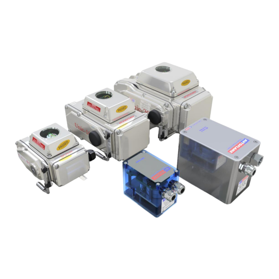
Autoflame offers three standard types of servomotors; small, large and industrial, each of which can be used for all control channels. Autoflame fuel and FGR valves require small or large servomotors only. All servomotors can be configured to drive clockwise or counterclockwise to open/close a valve or damper. -
Page 7: Servomotor Sizes
With Autoflame supplied valves, the correct servomotor size is already specified by Autoflame. To correctly size an Autoflame servomotor for use with a third party valve or damper, the torque required to drive that valve or damper should be checked. This is in order to select a servomotor with sufficient torque to drive the damper reliably. -
Page 8: Small Servomotors
Small Servomotors SMALL SERVOMOTORS Small servomotors provide a maximum torque of up to 4Nm, they are compact, lightweight, extremely durable and can be used for variety of applications including controlling air dampers, gas and oil fuel valves. The housing is made from high impact Acrylonitrile Butadiene Styrene (ABS) for lighter weight and easier installation. -
Page 9: External View
Small Servomotors 2.2. External View Autoflame Servomotors Guide Page | 9... -
Page 10: Dimensions
Small Servomotors 2.3. Dimensions All dimension in millimetres: 1 inch = 25.4 mm Autoflame Servomotors Guide Page | 10... -
Page 11: Large Servomotor
0.2 to 0.4 Nm Body mounting screws 2 x M5x25 Stainless socket head 1.2 – 2.6Nm Body mounting torque Shipped Weight (Polycarbonate) 1.75 kgs. (3.85 lbs) Shipped Weight (Metal version) 1.85 kgs. (4.1 lbs) Autoflame Servomotors Guide Page | 11... -
Page 12: External View - Metal Housing
Large Servomotors 3.2. External View – Metal Housing Autoflame Servomotors Guide Page | 12... -
Page 13: Dimensions - Metal Housing
Large Servomotors 3.3. Dimensions – Metal Housing All dimension in millimetres: 1 inch = 25.4 mm Autoflame Servomotors Guide Page | 13... -
Page 14: External View - Polycarbonate Housing
Large Servomotors 3.4. External View – Polycarbonate Housing Autoflame Servomotors Guide Page | 14... -
Page 15: Dimensions - Polycarbonate Housing
Large Servomotors 3.5. Dimensions – Polycarbonate Housing All dimension in millimetres: 1 inch = 25.4 mm Autoflame Servomotors Guide Page | 15... -
Page 16: 20Ma Small & Large Servomotors
Figure 1 Mechanical Construction The Autoflame 4-20mA Servomotors come from the factory set to 230V input and with the drive shaft set to operate in a clockwise direction from a horizontal starting position when viewed from the bottom as shown in Figure 1 above. - Page 17 4-20mA Small and Large Servomotors To change the required voltage, the Mains Select switch is toggled (see Figure 2). Ensure that the correct voltage is selected before applying mains voltage. Note that applying 230V with the switch set to 110V will cause the mains fuse on the unit to blow.
- Page 18 4-20mA Small and Large Servomotors Figure 4 - Calibration Mode Whilst in CAL mode, the DIR switch may be changed to alter the direction of rotation. The unit will rotate 90° clockwise, or anti-clockwise from the start position for the two positions of the DIR switch.
- Page 19 4-20mA Small and Large Servomotors Once set up, the unit will drive to a given angle as required by a 4-20mA signal on the Yellow and Green wires, where 4mA represents 0° and 20mA represents 90°. The corresponding 4-20mA angle of the potentiometer is produced on the Red and Blue wires and may be used to monitor that the servomotor is driving to the desired angle by confirming that the feedback control current matches the drive control current.
-
Page 20: Industrial Unic Servomotors
MM10078 UNIC40 MM10078/110 * Note: Solid state relays are recommended to be used with UNIC 20 and UNIC 40. (MM90070/RK) 24V DC version is available for use with Autoflame Bottom Blowdown Modules: UNIC Voltage V DC Torque Nm Torque ft lb... -
Page 21: Specifications
4.5Kg 7.8Kg 8.5Kg Rotation angle Mechanical Adjustable Adjustable Adjustable stopper Rated current 0.25/0.30A 0.30/0.35A 0.50/0.55A 0.7/0.9A (230V version) Rated current 0.6/0.7A 0.60/0.65A 1.0/1.1A 1.6/1.8A (120V version) Rated current 0.7/0.9A 0.65/0.70A 1.1/1.2A 1.8/2.0A (110V version) Autoflame Servomotors Guide Page | 21... -
Page 22: External Drawings
Industrial Servomotors 5.2. External Drawings Autoflame Servomotors Guide Page | 22... -
Page 23: Unic05
Industrial Servomotors 5.3. UNIC05 All dimension in millimetres: 1 inch = 25.4 mm Autoflame Servomotors Guide Page | 23... -
Page 24: Unic10
Industrial Servomotors 5.4. UNIC10 All dimension in millimetres: 1 inch = 25.4 mm Autoflame Servomotors Guide Page | 24... -
Page 25: Unic20 & Unic40
Industrial Servomotors 5.5. UNIC20 & UNIC40 All dimension in millimetres: 1 inch = 25.4 mm Autoflame Servomotors Guide Page | 25... -
Page 26: Manual Operation
Industrial Servomotors 5.6. Manual Operation Autoflame UNIC servomotors can be turned manually. Before starting manual operation, the power to the servomotor must be isolated/ switched off, failing to do so can cause serious injury and will permanently damage the servomotor. -
Page 27: Solid State Relays
The Solid-State Relays Earth through the Din Rail Mounts. An additional Earthing point is provided in the Heatsink, found on the input end, at the din rail mounting level. (This is marked as ). Autoflame Servomotors Guide Page | 27... -
Page 28: Industrial Servomotors 4-20Ma
Please Note The 4-20mA versions of the Industrial servomotors can only be used in the supplied configuration, when used with the Autoflame controller or I/O module. The default settings for these motors are 4mA = Closed, 20mA = Open There is a switch that can reverse the drive of the servo, BUT this does not reverse the feedback output, which... -
Page 29: Atex Approved Servomotors
ATEX Approved Servomotors ATEX APPROVED SERVOMOTORS Special versions of Autoflame servomotors are available with ATEX approval for use in hazardous environments where Explosion Proof equipment is required. 6.1. ATEX Certification The following instructions are specific to hazardous area installations (in accordance with IEC 60079-0:2011... - Page 30 Tightening torque, min 0.5 Nm and max 0.6 Nm • Insulated ferule type connectors or equivalent connectors shall be used for external connections. • The potentiometer connections (+V, 0V and W) shall only be terminated to an Autoflame MM Controller. Autoflame Servomotors Guide Page | 30...
-
Page 31: Atex Approved Small Servomotors
ATEX Approved Servomotors 6.2. ATEX Approved Small Servomotors The following ATEX approved small servomotors are available: Voltage V AC Frequency Torque Nm Supplied Wiring Glands Part # 50Hz 2x PG11 ATEX Glands MM10005/EXP 50Hz 1x PG11 - 1/2" NPSM ADAPTOR,... - Page 32 ATEX Approved Servomotors All dimension in millimetres: 1 inch = 25.4 mm Autoflame Servomotors Guide Page | 32...
-
Page 33: Atex Approved Large Servomotors
MM10004/EXP 110V 50/60Hz 2x M20 ATEX Glands MM10004/A/EXP 50/60Hz 2x M20 ATEX Glands MM10004/D/EXP ATEX approved large servomotor Note: ATEX certified glands must be used for the ATEX approval to apply to the servomotor. Autoflame Servomotors Guide Page | 33... - Page 34 ATEX Approved Servomotors All dimension in millimetres: 1 inch = 25.4 mm Autoflame Servomotors Guide Page | 34...
-
Page 35: Atex Approved Industrial Servomotors
ATEX Approved Servomotors 6.4. ATEX Approved Industrial Servomotors An ATEX approved Industrial UNIC10 servomotor is available. Voltage AC Frequency Torque Supplied Wiring Glands Part # 230V 50/60Hz MM10072/EXP 120V 50/60Hz MM10072/110/EXP UNIC10 Servomotor – ATEX Autoflame Servomotors Guide Page | 35... - Page 36 ATEX Approved Servomotors All dimension in millimetres: 1 inch = 25.4 mm Autoflame Servomotors Guide Page | 36...
-
Page 37: Servomotors Mounting Brackets
Servomotor Mounting Brackets SERVOMOTORS MOUNTING BRACKETS Servomotors mounting brackets and couplings are used to mount the Autoflame servomotor to third party valves or dampers. The servomotor can be mounted directly, and the supplied screws are used to fix the servomotor to the bracket. -
Page 38: Small Servomotor Mounting Bracket And Coupling
Servomotor Mounting Brackets 7.1. Small Servomotor Mounting Bracket and Coupling Autoflame Servomotors Guide Page | 38... -
Page 39: Large Servomotor Mounting Bracket And Coupling
Servomotor Mounting Brackets 7.2. Large Servomotor Mounting Bracket and Coupling Autoflame Servomotors Guide Page | 39... -
Page 40: Unic05 Mounting Bracket And Coupling
Servomotor Mounting Brackets 7.3. UNIC05 Mounting Bracket and Coupling Autoflame Servomotors Guide Page | 40... -
Page 41: Unic10 Mounting Bracket And Coupling
Servomotor Mounting Brackets 7.4. UNIC10 Mounting Bracket and Coupling Autoflame Servomotors Guide Page | 41... -
Page 42: Unic20 / Unic40 Mounting Bracket And Coupling
Servomotor Mounting Brackets 7.5. UNIC20 / UNIC40 Mounting Bracket and Coupling Autoflame Servomotors Guide Page | 42... -
Page 43: Installation
Installation INSTALLATION 8.1. Overview Autoflame servomotors are supplied set at 0.0° position as standard. It is crucial to remember that this position may not necessarily position the damper at 0.0° or a closed position automatically. This must be physically checked. -
Page 44: Wiring
8.2. Wiring The servomotors can be configured to rotate in clockwise or counterclockwise direction, please refer to the wiring diagram below as an example for wiring a small servomotor to Channel 1 on a Mk8 MM. Clockwise Rotation Counter-Clockwise Rotation... -
Page 45: Adjusting The Servomotor's Position
Remove the servomotor’s terminal cover by loosening the 4 screws holding the cover. On Autoflame gas, oil and gas/oil piggy-back valves it is necessary to remove the servomotor. Manually position the oil/gas valve slot to its closed position. Observe the position of the drive pin on the servomotor. -
Page 46: Servomotor Feedback Voltage
= 3.3V = 3.6V Servo Visible Operating Range = 0.21V = 0V Standard Direction = 3.3V = 3.6V Servo Visible Operating Range = 0.21V = 0V Reversed Direction Autoflame Servomotors Guide Page | 46... -
Page 47: Servomotors With Autoflame Gas Valves
Installation 8.5. Servomotors with Autoflame Gas Valves On threaded valves, the pin on the top of the valve is 90° opposite from the position of the butterfly valve. On flanged valves, the pin on the top of the valve is in line with the position of the butterfly valve. -
Page 48: Servomotor Flying Leads And Connectors
An enclosure mounted connectors and flying leads kit is available for easy installation and replacement of the servomotors. This is available for small and large servomotors only. This kit provides IP65/NEMA4 ingress protection to the servomotors. the wires are screened, and they provide protection for the servomotor’s signal from electrical noise and interference. -
Page 49: Maintenance And Troubleshooting
Maintenance and Troubleshooting MAINTENANCE AND TROUBLESHOOTING It is good practice to check the Autoflame equipment periodically for the integrity of the installation. An important aspect of the system installation is the mechanical assemblies associated with the servomotors, i.e. mounting brackets and couplings. The servomotor checks could include: •... - Page 50 AUTOFLAME SERVOMOTORS GUIDE 12.08.2024 Autoflame Engineering Ltd. Unit 1-2 Concorde Business Centre Airport Industrial Estate, Wireless Road Biggin Hill, Kent TN16 3YN United Kingdom Tel: +44 (0)1959 578 820 Email: technicalsupport@autoflame.com Website: www.autoflame.com...
Need help?
Do you have a question about the Small and is the answer not in the manual?
Questions and answers