Advertisement
Quick Links
Q
S
G
UICK
TART
UIDE
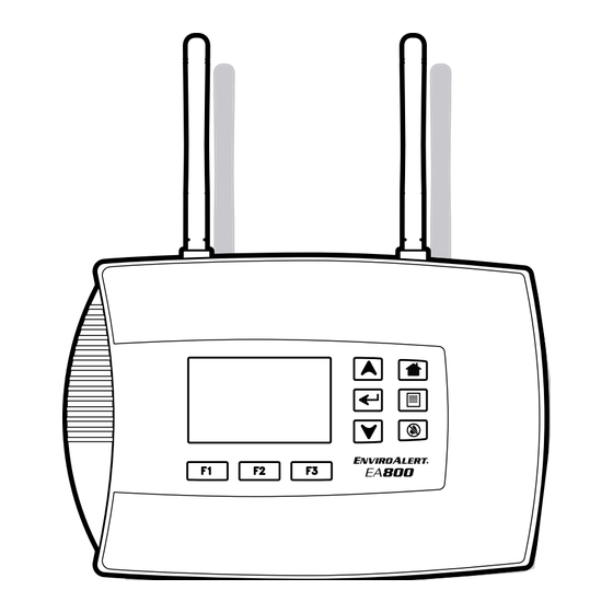
This guide provides basic setup instructions for the EA800
Environmental Monitoring System and associated sensors.
Installers should refer to the Installation Manual (found
on the CD and online at www.ea800.net) for complete
instructions and specifications, and to become familiar with
the many features provided by the EA800. The EA800 allows
connection of up to 4 hardwired and 4 wireless sensors.
R
I
/O
EAD THE
NSTALLATION
WNER
Installation/Owner's Manual can be found on the enclosed CD and online at www.ea800.net
• All power terminals must be connected to a Class 2 power limited circuit complying with
National Electrical Code NFPA 70, Article 725. Where required, this equipment is to be
isolated from the main supply by a limited power source as specified in EN60950.
• Batteries shall not cause explosion or produce a fire HAZARD as a result of excessive charge
or discharge,
• Ensure all wiring for wired sensor connections is done before powering on or
programming the EA800 base console.
• If the equipment is used in a manner not specified by the manufacturer, the protection
provided by the equipment may be impaired.
I
O
NSTALLATION
VERVIEW
1. Installing Base Console
Using a terminal block adapter, connect power supply + and - leads to POWER IN (+) and
(-) on J5. Observe proper polarity. If using a transformer, ensure that the transformer is an
isolated power supply.
EA800 Input Voltage: +11 to +26VDC at ≤ 500mA current draw
Note: The input voltage specification does not include requirements for loads connected to
Aux Power Out.
If Aux Power Out is to be used, connect + and - leads to AUX POWER OUT (+) and (-)
on J5 using a terminal block adapter. When base console is powered up, a 30-minute timer
starts. The console will alarm after this timer expires unless 1 or more sensors are installed.
'
M
S
ANUAL FOR COMPLETE INSTRUCTIONS
Do not connect or disconnect power, sensor, or alarm wiring
while power is applied. Connecting and disconnecting the
EA800 base console with power connected may damage the
base console or result in improper or unreliable operation.
Connection of unsuitable loads to this connection may
damage the power supply and EA800 base console, or result
in improper or unreliable operation.
(800) 635-4269 • (507) 625-7231 P • (507) 387-2488 F
S
PECIFICATIONS
EA800 Console Input Voltage
.
Wireless Sensor Input Voltage
(EA-WMFS, EA-WTS, EA-WHS)
EA800 Console Auxiliary Output
Voltage
Environmental Operating Range
(EA800, EA-WMFS, EA-WTS,
EA-WHS)
Ambient Environmental Quality
Relay Contact Ratings
EA800 Real-Time Clock Battery
J5
Power
Aux Power
In
Out
VIEW OF CIRCUIT BOARD IN EA800 BASE CONSOLE
1
2
3
NO COM NC NO COM NC NO COM NC NO COM NC NO COM NC NO COM NC
J8
1950 Excel Drive • Mankato, MN 56001 USA
(Tech Support 8:00am - 5:00pm CST)
www.winland.com
+11 to +26VDC @ ≤ 500mA current draw
+12VDC @ ≤ 100mA current draw via 2.1 mm barrel plug,
center positive OR 2xAA Alkaline Batteries (1.5V Cell)
Equivalent to DC Input Voltage used: +11 to +26VDC.
(Maximum output current 0.5A).
Temperature: 0°C to 50°C (32°F to 122°F). Not for
installation inside coolers or freezers.
Humidity: 5% to 95% RH, non-condensing.
Indoor use intended, non-corrosive environment.
Max 30VDC @ 1 amp resistive
CR2032 (3V Cell)
J6
1
2
3
4
Hard Wired Sensor Inputs
Relay Outputs
4
5
6
7
8
NO COM NC NO COM NC
NO COM NC
J9
J10
D-011-0153 Rev D (04/2011)
Aux
Advertisement

Subscribe to Our Youtube Channel
Related Manuals for Winland Electronics ENVIROALERT EA800


Summary of Contents for Winland Electronics ENVIROALERT EA800
- Page 1 UICK TART UIDE This guide provides basic setup instructions for the EA800 1950 Excel Drive • Mankato, MN 56001 USA Environmental Monitoring System and associated sensors. (Tech Support 8:00am - 5:00pm CST) Installers should refer to the Installation Manual (found (800) 635-4269 •...
- Page 2 2. Unlocking/Locking Base Console screen does not contain the number found on the sensor’s PC board, press F1 (Cancel) to continue the search process. Select the output relay to which the wireless sensor is to be connected, then Press F1 to unlock base console. The default password press ...
Need help?
Do you have a question about the ENVIROALERT EA800 and is the answer not in the manual?
Questions and answers