
Related Manuals for Trime MGTP 60 SS KR

Summary of Contents for Trime MGTP 60 SS KR
- Page 1 USER’S MANUAL Model: RP354-60TS4 User’s manual: RP354-60TS4 Rev.00 Date: 26/03/2024...
- Page 2 It is also recommended to use only original factory spare parts Reproduction of this manual is not permitted, unless written approval is obtained from factory. Trime S.r.l. Strada per Robecco 20081 Cassinetta di Lugagnano (MI) Italy. Tel. +39029421724 - e-mail: info@trime.it - Internet: www.trime.it...
-
Page 3: Table Of Contents
TABLE OF CONTENTS SAFETY RULES ....................................4 SAFETY PRECAUTIONS TO BE OBSERVED .............................. 4 FIRE PRECAUTIONS ....................................4 FLAMMABLE FLUID PRECAUTIONS ............................... 4 ELECTRICAL HAZARD ..................................... 5 LUBRICATION AND SERVICING ................................5 SAFETY STICKERS GUIDE ..................................6 TECHNICAL SPECIFICATIONS ................................7 GENERATOR IDENTIFICATION ................................ -
Page 4: Safety Rules
SAFETY RULES SAFETY PRECAUTIONS TO BE OBSERVED Read this manual and learn the operating characteristics and limitations of the machine before operating it. The manufacturer declines all liability for injury to persons and damage to components due to not respecting the safety rules. Report all malfunctions to a maintenance responsible. -
Page 5: Electrical Hazard
SAFETY RULES ELECTRICAL HAZARD DO NOT smoke or allow open flames or sparks near the batteries. Before doing repair works, ALWAYS disconnect batteries. Disconnect negative terminal first and reconnect last. Before carrying out any welding on the machine, ALWAYS make sure to disconnect batteries and alternator leads. ... -
Page 6: Safety Stickers Guide
SAFETY RULES SAFETY STICKERS GUIDE Safety stickers meanings Attention! Read user’s manual before Attention, high voltage! Read user’s manual operating the machine. before operating the machine. extinguish with water! Attention, don’t touch the moving Attention! Danger of crushing. parts. Attention! liquid Lifting point. -
Page 7: Technical Specifications
TECHNICAL SPECIFICATIONS GENERATOR IDENTIFICATION MGTP 60 SS KR DIESEL ENGINE DRIVEN Strada per Robecco - 20080 Cassinetta di Lugagnano (MI) Italy tel. +39 02 9421724 OWNER'S MANUAL SERIAL N° IP 21 I.CL. H 1500 XXXXXXXXX DRY WEIGHT 1538 kg RP354-60TS4 Information regarding the machine model, are on the unit serial number plate. -
Page 8: Technical Data
TECHNICAL DATA Engine KOHLER KDI-TCN Model 3404E5/22 Governor Electronic Cylinders number Displacement 3359 Engine speed (rpm) 1500 rpm Cooling system Liquid Generator Model STAMFORD S1L2-Y1 Rated output 60kVA – 400V Power available to auxiliary socket 60kVA – 400V Rated frequency 50Hz General informations Noise level... -
Page 9: Machine Layout
MACHINE LAYOUT 2243 1212 RP354-60TS4 Revision Level 00 – 26/03/2024 Manual Code –... -
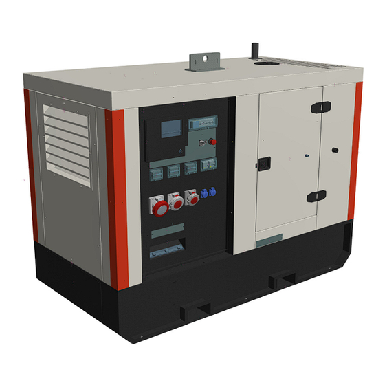
Page 10: Machine Components
MACHINE COMPONENTS 1. Generator access panel 2. Battery inside 3. Control panel 4. Emergency stop 5. Engine access door 6. Exhaust access door 7. Fuel filler inside 8. Forklift pockets 9. Engine access door 10. Lifting hook 11. Exhaust exit 12. - Page 11 TECHNICAL SPECIFICATIONS CONTROL PANEL 1. DSE control unit 17. 32A 400V outlet socket 2. ELR 18. 16A 400V outlet socket 3. Main circuit breaker 19. 16A 220V outlet Shuko 4. DSE supplying switch 20. 16A 220V outlet Shuko 5. Regeneration button 21.
-
Page 12: Control Devices
TECHNICAL SPECIFICATIONS CONTROL DEVICES DSE 7310 manual & auto start control module DSE 7310 an compact control module that provides comprehensive range of features for single-set applications. controller can be used in manual or auto start mode. Emergency stop button Engine oil drain manual pump The machine is fitted with a The machine is fitted with a manual pump as... -
Page 13: Handling And Transport
HANDLING AND TRANSPORT HANDLING AND TRANSPORT WITH CRANE Handling by crane is allowed only if the machine is connected to the crane through the lifting eye. Ensure that the lifting capacity of the crane and lifting devices is suited to the weight of the machine to move. The weight is specified in the provided documentation (user’s manual) and on the data plate. -
Page 14: Preliminary Check & Starting
PRELIMINARY CHECK & STARTING Before starting and operating the unit, we suggest making the following routine checks for improved safety, better efficiency, longer product life and in order to avoid work disruptions. Check that the machine is leveled correctly and stabilized firmly. ... -
Page 15: Generator Use
GENERATOR USE DSE 7310 MODULE: DESCRIPTION OF CONTROLS Name Function Navigation Move the selector up and down on the screen. Display Graphical Alarm LED The LED is red when there is an active alarm Open generator (only manual mode) Open Stop Stops the genset if manual or auto mode is selected. -
Page 16: Manual Mode
GENERATOR USE MANUAL MODE 1. Ensure that the battery switch is in ON position. 2. Ensure that the emergency STOP is in correct position. 3. Put the ON/OFF selector in ON position. 4. On DSE press button 6, then press button 9. 5. -
Page 17: Regeneration
GENERATOR USE REGENERATION The STAGE V engine equip a DPF that, depending from the soot level needs to be regenerated periodically. AUTOMATIC REGENERATION During the normal functioning of the machine, the engine will periodically perform an automatic regeneration cycle. Never stop the machine when the automatic regeneration cycle is on going. During the automatic regeneration the DSE monitor will show: MANUAL REGENERATION If the automatic regeneration fail several times, or however when the soot level reach the 105%, the engine will ask a manual... - Page 18 GENERATOR USE Keep pushed for some seconds the DPF REGENERATION button (n°5 pct.2.2), until on the DSE monitor will appear The main circuit breaker will open, and the regeneration will start. We strongly suggest to do not close the main circuit breaker during the regeneration. After the regeneration ends (about 30/40 minutes), it will be possible to restart the normal working.
-
Page 19: Routine Maintenance
ROUTINE MAINTENANCE Poorly maintained equipment can become a safety hazard. In order, for the equipment, to operate safely and properly over a long period of time, periodic maintenance and occasional repairs are necessary. Any kind of maintenance work on the machine must be carried out by Authorized and trained personnel. It should be done in a safe working environment and with the machine well stabilized. -
Page 20: Spare Parts
SPARE PARTS BASEFRAME RP354-60TS4 Revision Level 00 – 26/03/2024 Manual Code –... - Page 21 SPARE PARTS BASEFRAME CODE DESCRIPTION 352-290 Lifting beam C003-019 Battery switch 352-499 Battery switch bracket 352-500 Battery switch bracket closure C003-1270 Valve C006-487 Fuel pump 352-316 Bracket C003-185 Fuel tank cap C001-687-229 Floating 352-293 Fuel tank 352-292 Alternator beam Z352-050 Battery closure Z016-247 Battery beam...
-
Page 22: Power Pack
SPARE PARTS POWER PACK CODE DESCRIPTION C011-324 STAMFORD S1L2-Y1 C003-041 Pump Z016-272 Pump bracket C006-495 KOHLER KDI-TCN 3404E5/22 C002-006 Shock absorber C001-1269 Resistor 2kW 491-555-SX Lexan bracket 391-394 Lexan 352-283 Resistors wiring cover 352-323 Wiring box C006-318 Kohler control unit C006-358 Kohler connector Z016-755... -
Page 23: Canopy
SPARE PARTS CANOPY RP354-60TS4 Revision Level 00 – 26/03/2024 Manual Code –... - Page 24 SPARE PARTS CANOPY CODE DESCRIPTION 352-286 Canopy top Z352-016 Lifting kook 352-492 Inox platen C003-777 Manhole 352-314 Cover 352-210 Rear left corner 352-299 Grid 352-211 Rear right corner C003-666 Female door stopper C003-667 Male door stopper C003-1035 Hinge 352-309 Door 352-452 Right band C003-020...
-
Page 25: Control Panel
SPARE PARTS CONTROL PANEL RP354-60TS4 Revision Level 00 – 26/03/2024 Manual Code –... - Page 26 SPARE PARTS CONTROL PANEL CODE DESCRIPTION CODE DESCRIPTION C003-1036 Lockage 397-039 Temperature sensor bracket Z352-020 Door C008-032 16 poles male connector C001-537 DSE 7310MKII Z016-756 Frame C003-715 Circuit breaker cover Z016-755 Wire crossing Z352-039 Circuit breaker platen C003-1157 Knob C001-261 Earth leakage relay 352-562 Wire stop...
-
Page 27: Alternator
SPARE PARTS ALTERNATOR RP354-60TS4 Revision Level 00 – 26/03/2024 Manual Code –... - Page 28 SPARE PARTS ALTERNATOR CODE DESCRIPTION S-A052E494 Cover, End S-A051P107 Brkt, End, F1, NDE S-45−0866 P0 Bearing Kit P0 S-A051L226 Str, Exc, 38.0 S-A051L227 Str, Exc, 45.0 S-A053F533 Str, Exc, 55.0 S-191−1064 P1 Wnd Ex Rtr 38 MM S-A051L228 Rtr, Exc, 45.0 S-A053F505 Rtr, Exc, 55.0 S-45−0427...
-
Page 29: Electrical Diagram
ELECTRICAL DIAGRAM RP354-60TS4 Revision Level 00 – 26/03/2024 Manual Code –... - Page 30 ELECTRICAL DIAGRAM RP354-60TS4 Revision Level 00 – 26/03/2024 Manual Code –...
-
Page 31: Warranty
WARRANTY The warranty period starts on the delivery date to the first purchaser. The machine is covered by warranty for one year from the above mentioned date. Only genuine parts should be used to carry out repairs. Failure to use only genuine parts may invalidate the manufacturer’s warranty. We reserve the right to request the warranty replaced parts back for analysis.
Need help?
Do you have a question about the MGTP 60 SS KR and is the answer not in the manual?
Questions and answers