Table of Contents
Advertisement
Advertisement
Table of Contents

Related Manuals for D-Link DI-514


Summary of Contents for D-Link DI-514
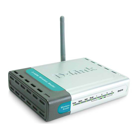
- Page 1 D-Link Air DI-514 2.4GHz Wireless Router Manual Building Networks for People...
-
Page 2: Table Of Contents
Package Contents ... 3 Introduction ... 4 Wireless Basics ... 8 Getting Started...11 Using the Configuration Menu ... 13 Troubleshooting ... 35 Networking Basics ... 40 Technical Specifications... 55 9. Technical Support... 57 10. Warranty... 58 11. Registration ... 62... -
Page 3: Package Contents
Printed Quick Installation Guide Note: Using a power supply with a different voltage rating than the one included with the DI-514 will cause damage and void the warranty for this product. If any of the above items are missing, please contact your reseller. -
Page 4: Introduction
IPSec and PPTP VPN sessions for telecommuters or for anyone who needs to transmit sensitive information more securely. The D-Link Air DI-514 is the ideal networking solution for small offices, home offices, schools, coffee shops and other small businesses that cater to the public. - Page 5 Connections Auto MDI/MDIX LAN ports automatically sense the cable type when connecting to Ethernet-enabled computers. The Auto MDI/MDIX WAN port is the connection for the Ethernet cable to the Receptor for the Cable or DSL modem. Power Adapter. Pressing the Reset Button restores the router to its original factory default settings.
-
Page 6: Features And Benefits
• Multiple Concurrent VPN Sessions – concurrent IPSEC and PPTP sessions, so multiple users behind the DI-514 can access corporate networks through various VPN clients more securely • Simple Setup Wizard for Easy Installation... - Page 7 LEDS STATUS LED - Blinks constantly to indicate device is functioning properly. POWER LED - A solid light indicates a proper connection WAN LED - to the power supply. A solid light indicates connection on the WAN port. This LED blinks during data transmission.
-
Page 8: Wireless Basics
Wireless Basics D-Link Air wireless products are based on industry standards to provide easy-to-use and compatible high-speed wireless connectivity within your home, business or public access wireless networks. D-Link wireless products will allow you access to the data you want, when and where you want it. - Page 9 MPEG format over your network without noticeable delays. The technology works by using multiple frequencies in the 2.4GHz range at speeds up to 11 Mbps. D-Link Air products will automatically sense the best possible connection speed to ensure the greatest speed and range possible...
- Page 10 The key to maximizing wireless range is to follow these basic guidelines: 1. Keep the number of walls and ceilings between the DI-514 and your receiving device (e.g., the DWL-650) to a minimum - each wall or ceiling can reduce your D-Link Air Wireless product’s range from 3 to 90 feet (1...
-
Page 11: Getting Started
There are basically two modes of networking. • Infrastructure – using a Wireless Router such as the DI-514, or an Access Point • Ad-Hoc – directly connecting to another computer, for peer-to-peer communication, using wireless network adapters on each computer, such as two or more DWL-650 wireless Cardbus adapters. - Page 12 Setting Up an Infrastructure Network Please remember that D-Link AirPlus wireless devices are pre-configured to connect together, right out of the box, with the default settings. You will need a broadband Internet access (Cable/DSL) subscription. Consult with your Cable/DSL provider for proper installation of the modem.
-
Page 13: Using The Configuration Menu
(The IP Address shown in the example above is the default setting. If you have changed the IP Address of the DI-514 to conform to a network, then input that IP Address in the web browser, instead of the default IP Address shown.) •... - Page 14 Home > Wizard Wireless Wireless Settings are settings for the (Access Point) Portion of the Wireless Router. Here you can change the wireless settings to fit an existing wireless network or to customize your wireless network. Home > Wireless...
- Page 15 Channel Indicates the channel setting for the DI-514. By default the channel is set to 6. The Channel can be changed to fit the channel setting for an existing wireless network or to customize the wireless network.
- Page 16 WAN is short for Wide Area Network. The WAN settings can be referred to as the Public settings. All IP information in the WAN settings are public IP addresses which are accessible on the Internet. The WAN settings consist of three main options: Dynamic IP Address, Static IP Address, and PPPoE.
- Page 17 Static IP Address Choose Static IP Address if all WAN IP information is provided to you by your ISP. You will need to enter in the IP address, subnet mask, gateway address, and DNS address(es) provided to you by your ISP. Each IP address entered in the fields must be in the appropriate IP form, which are four IP octets separated by a dot (x.x.x.x).
- Page 18 PPPoE Please be sure to remove any Client Software program on your computer before you start your configuration of the DI-514 Router. Choose PPPoE (Point to Point Protocol over Ethernet) if your ISP uses PPPoE connection. Your ISP will provide you with a username and password.
- Page 19 LAN is short for Local Area Network. This is considered your internal network. These are the IP settings of the LAN interface for the DI-514. These settings may be referred to as Private settings. You may change the LAN IP address if needed.
- Page 20 Home > DHCP DHCP DHCP stands for Dynamic Host Control Protocol. The DI-514 has a built-in DHCP server. The DHCP Server will automatically assign an IP address to the computers on the LAN/private network. Be sure to set your computers to be DHCP clients by setting their TCP/IP settings to “Obtain an IP Address...
- Page 21 Advanced > Virtual Server Virtual Server The DI-514 can be configured as a virtual server so that remote users accessing Web or FTP services via the public IP address can be automatically redirected to local servers in the LAN (Local Area Network).
- Page 22 assigning the server IP to use that particular virtual service. Name: The name referencing the virtual service. Private IP: The server computer in the LAN (Local Area Network) that will be providing the virtual services. Protocol Type: The protocol used for the virtual service. Private Port: The port number of the service used by the Private IP computer.
- Page 23 Internet telephony and others. These applications have difficulties working through NAT (Network Address Translation). Special Applications makes some of these applications work with the DI-514. If you need to run applications that require multiple connections, specify the port normally associated with an application in the "Trigger Port"...
- Page 24 The DI-514 provides some predefined applications in the table on the bottom of the web page. Select the application you want to use and enable it. Note! Only one PC can use each Special Application tunnel. Trigger Name: This is the name referencing the special application.
- Page 25 MAC Filters Use MAC (Media Access Control) Filters to allow or deny LAN (Local Area Network) computers by their MAC addresses from accessing the Internet. You can either manually add a MAC address or select the MAC address from the list of clients that are currently connected to the Broadband Router.
- Page 26 Domain Blocking Domain Blocking is used to allow or deny LAN (Local Area Network) computers from accessing specific domains on the Internet. Domain blocking will deny all requests to a specific domain such as http and ftp. It can also allow computers to access specific sites and deny all other...
- Page 27 If you have a client PC that cannot run Internet applications properly from behind the DI-514, then you can set the client up to unrestricted Internet access. It allows a computer to be exposed to the Internet. This feature is useful for gaming purposes.
- Page 28 Advanced > Performance Beacon Interval - Beacons are packets sent by an Access Point to synchronize a wireless network. Specify a value. 100 is the default setting and is recommended. RTS Threshold - This value should remain at its default setting of 2432. If inconsistent data flow is a problem, only a minor modification should be made.
- Page 29 Open System - The DI-514 will be visible to all devices on the network. This is the default setting. Shared Key - In this mode, in order to access the DI-514 on the network, the device must be listed in the MAC Address Control List.
- Page 30 Broadband Router and 8080 is the port used for the Web-Management interface. Time The system time is the time used by the DI-514 for scheduling services. You can manually set the time or connect to a NTP (Network Time Protocol) server. If an NTP server is set, you will only need to set the time zone.
- Page 31 Click on Browse to browse the local hard drive and locate the firmware to be used for the update. Please check the D-Link support site for firmware updates http://support.dlink.com. Tools > Misc Miscellaneous Items...
- Page 32 Block WAN Ping - When you “Block WAN Ping”, the DI-514 will not respond to ping commands from the Internet. Pinging public WAN IP addresses is a common method used by hackers to test whether your WAN IP address is valid.
- Page 33 • IP Address: LAN/Private IP Address of the DI-514 • Subnet Mask: LAN/Private Subnet Mask of the DI-514 • IP Address: WAN/Public IP Address • Subnet Mask: WAN/Public Subnet Mask • Gateway: WAN/Public Gateway IP Address • Domain Name Server: WAN/Public DNS IP Address •...
- Page 34 Email Address - The email address the logs will be sent to. Click on Email Log Now to send the email. Status > Stats Traffic Statistics The Broadband Router keeps statistics of traffic that passes through it. You are able to view the amount of packets that passes through the Router on both...
-
Page 35: Troubleshooting
Windows XP in the Networking Basics section of this manual. Note: The IP Address of the DI-514 is 192.168.0.1. All the computers on the network must have a unique IP Address in the same range, e.g., 192.168.0.x. and a Subnet Mask of 255.255.255.0. Any computers that have identical IP Addresses will not be visible on the network. - Page 36 • Check that the IP Address assigned to the wireless adapter is within the same IP Address range as the gateway. Since the DI-514 has an IP Address of 192.168.0.1, wireless adapters must have an IP Address in the same range, e.g., 192.168.0.x.
- Page 37 3. Check that the drivers for the network adapters are installed properly. You may be using different network adapters than those illustrated here, but this procedure will remain the same, regardless of the type of network adapters you are using. •...
- Page 38 • Look under Device Status to check that the device is working properly. • Click OK D-Link Air DWL-650 Wireless Cardbus Adapter D-Link AirPlus DWL-650+ Wireless Cardbus Adapter D-Link AirPlus DWL-650 Wireless Cardbus Adapter...
- Page 39 Remember that D-Link Plus products network together, out of the box, at the factory default settings. To hard-reset the D-Link Plus DI-514 to Factory Default Settings, please do the following: • Leave the device powered on, do not disconnect the power •...
-
Page 40: Networking Basics
Networking Basics Using the Network Setup Wizard in Windows XP In this section you will learn how to establish a network at home or work, using Microsoft Windows XP. Note: Please refer to websites such as http://www.homenethelp.com http://www.microsoft.com/windows2000 for information about networking computers using Windows 2000, ME or 98. - Page 41 Networking Basics Please follow all the instructions in this window: Click Next In the following window, select the best description of your computer. If your computer connects to the internet through a gateway/router, select the second option as shown. Click Next...
- Page 42 Networking Basics Enter a Computer description and a Computer name (optional.) Click Next Enter a Workgroup name. All computers on your network should have the same Workgroup name. Click Next...
- Page 43 Networking Basics Please wait while the Network Setup Wizard applies the changes. When the changes are complete, click Next. Please wait while the Network Setup Wizard configures the computer. This may take a few minutes.
- Page 44 Networking Basics In the window below, select the best option. In this example, Create a Network Setup Disk has been selected. You will run this disk on each of the computers on your network. Click Next. Insert a disk into the Floppy Disk Drive, in this case drive A. Format the disk if you wish, and click Next.
- Page 45 Networking Basics Please wait while the Network Setup Wizard copies the files. Please read the information under Here’s how in the screen below. After you complete the Network Setup Wizard you will use the Network Setup Disk to run the Network Setup Wizard once on each of the computers on your network.
- Page 46 Networking Basics Please read the information on this screen, then click Finish to complete the Network Setup Wizard. The new settings will take effect when you restart the computer. Click Yes to restart the computer. You have completed configuring this computer. Next, you will need to run the Network Setup Disk on all the other computers on your network.
- Page 47 Naming your Computer To name your computer, please follow these directions: In Windows XP: • Click Start (in the lower left corner of the screen) • Right-click on My Computer • Select Properties and click • Select the Computer Name Tab in the System Properties window.
- Page 48 Naming your Computer • In this window, enter the Computer name. • Select Workgroup and enter the name of the Workgroup. • All computers on your network must have the same Workgroup name. • Click OK Checking the IP Address in Windows XP The wireless adapter-equipped computers in your network must be in the same IP Address range (see Getting Started in this manual for a definition of IP Address Range.) To check on the IP Address of the adapter, please do...
- Page 49 Checking the IP Address in Windows XP This window will appear. • Click the Support Tab • Click Close Assigning a Static IP Address in Windows XP/2000 Note: Residential Gateways/Broadband Routers will automatically assign IP Addresses to the computers on the network, using DHCP (Dynamic Host Configuration Protocol) technology.
- Page 50 Assigning a Static IP Address in Windows XP/2000 • Double-click on Network Connections • Right-click on Local Area Connections. • Double-click Properties...
- Page 51 IP Address: e.g., 192.168.0.2 Subnet Mask: 255.255.255.0 Default Gateway: Enter the LAN IP Address of the wireless router. (D-Link wireless routers have a LAN IP address of 192.168.0.1) • Select Use the following DNS server addresses. Enter the LAN IP address of the wireless router.
- Page 52 Assigning a Static IP Address with Go to the Apple Menu and select System Preferences. Click on Network Select Built-in Ethernet in the Show pull-down menu. Select Manually in the Configure pull-down menu. Input the Static IP Address, the Subnet Mask and the Router IP Address in the appropriate fields.
- Page 53 Selecting a Dynamic IP Address with Go to the Apple Menu and select System Preferences. Click on Network Select Built-in Ethernet in the Show pull-down menu. Select Using DHCP in the Configure pull-down menu. Click Apply Now The IP Address, Subnet mask, and the Router’s IP Address will appear in a few seconds.
- Page 54 Checking the Wireless Connection by Pinging For Windows XP and 2000: Go to Start > Run > type cmd. A window similar to Fig. 9.25 will appear. Type ping xxx.xxx.xxx.xxx, where xxx is the IP address of the Wireless Router or Access Point.
-
Page 55: Technical Specifications
Standards • IEEE b • IEEE 802.3 • IEEE 802.3u VPN Pass Through / Multi-Sessions • PPTP • L2TP • IPSec Device Management Web-Based – Internet Explorer v6 or later; Netscape Navigator v6 or later; or other Java- enabled browsers. Wireless Data Rates With Automatic Fallback •... - Page 56 • 2Mbps(DQPSK) • 1Mbps(DBPSK) Wireless Transmit Power 15dBm ± 2dB External Antenna Type Single detachable reverse SMA LEDs • Power • M1 • M2 • WAN • Local Network—10/100 • WLAN (Wireless Connection) Operating Temperature 32°F to 131°F ( 0°C to 55°C) Humidity 95% maximum (non-condensing) Power Input...
-
Page 57: Technical Support
Technical Support You can find software updates and user documentation on the D-Link website. D-Link provides free technical support for customers within the United States and within Canada for the duration of the warranty period on this product. U.S. and Canadian customers can contact D-Link Technical Support through our... -
Page 58: Warranty
D-Link’s sole obligation shall be to repair or replace the defective Hardware during the Warranty Period at no charge to the original owner or to refund at D-Link’s sole discretion. Such repair or replacement will be rendered by D-Link at an Authorized D-Link Service Office. The replacement Hardware need not be new or have an identical make, model or part. - Page 59 D-Link. Products shall be fully insured by the customer. D-Link will not be held responsible for any packages that are lost in transit to D-Link. The repaired or replaced packages will be shipped to the customer via UPS Ground or any common carrier selected by D-Link, with shipping charges prepaid.
- Page 60 Trademarks: D-Link is a registered trademark of D-Link Systems, Inc. Other trademarks or registered trademarks are the property of their respective manufacturers or owners.
-
Page 62: Registration
11. Registration Register your D-Link product online at http://support.dlink.com/register/ 10/11/04...
Need help?
Do you have a question about the DI-514 and is the answer not in the manual?
Questions and answers