Table of Contents
Advertisement
Quick Links
Advertisement
Table of Contents
Troubleshooting

Related Manuals for Fastech Ezi-Speed ST


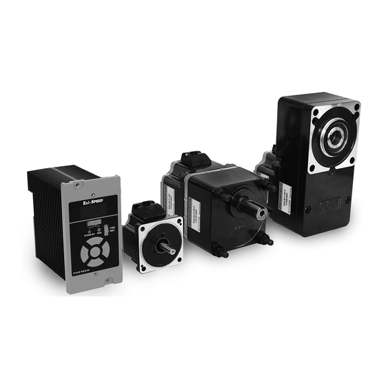
Summary of Contents for Fastech Ezi-Speed ST
-
Page 2: Table Of Contents
Table of contents Safety Pre-cautions ........................5 ※ Before operation .......................... 5 ※ Precautions ............................. 5 2. Characteristics ............................. 9 2.1 Part number..........................9 2.2 Combinations ..........................10 2.3 Checking the parts ......................... 13 3. Specifications and dimensions of the drive ................ 14 3.1 Specifications .......................... - Page 3 6.3.5 Life time of Gearhead and Service factor .............. 46 6.3.6 Maximum permissible torque of gearhead ............46 6.3.7 Permissible overhung load and permissible thrust load ......... 47 6.4 Installing the combination hollow shaft gearhead ..........48 6.4.1 Checking the parts ......................48 6.4.2 Cautions on operations....................
- Page 4 8. Convenient functions ........................78 8.1 Function list ..........................78 8.2 Setting and 7-segments display ..................80 8.3 Parameter list ..........................87 8.4 Display on the drive ....................... 90 8.5 Setting the operation data ....................93 8.6 Setting the acceleration time and deceleration time ..........94 8.7 Setting of torque limit ......................
-
Page 5: Safety Pre-Cautions
Thoroughly read the manual provided with the purchased Ezi-SPEED • When the manual is damaged or lost, please contact with FASTECH’s agents or our company at the address on the last page of the manual. - Page 6 • Although precaution is only a Attention, a serious result could be caused depending on the situation. Please follow safety precautions. • Checking the product Check if the product is damaged or parts are missing. Otherwise, the machine may get damaged or the user may get injured. Semiconductor device was used in Drive.
- Page 7 Use a connection cable (Option) when extending the wiring distance the motor and drive. Prevent leakage current Stray capacitance exists between the drive’s cable and other cables, the earth and the motor, respectively. A high-frequency current may leak out through such capacitance having a determental effect on the surrounding equipment.
- Page 8 Cautions when using low temperature environment. When an ambient temperature is low, since the load torque may increase by oil seal or viscosity increment of grease used in the gearhead, the output torque may decrease or overload alarm may generate. However, as time passes, the oil seal or grease is warmed up, and the motor can be driven without generating and overload alarm.
-
Page 9: Characteristics
2. Characteristics 2.1 Part number... -
Page 10: Combinations
2.2 Combinations Standard Motor and Drive Combinations Unit Part Number Motor Part Number Drive Part Number Ezi-SPEED-60-S-30-A ESD-30-A ESM-60-S-30 Ezi-SPEED-60-S-30-C ESD-30-C Ezi-SPEED-80-S-60-A ESD-60-A ESM-80-S-60 Ezi-SPEED-80-S-60-C ESD-60-C Ezi-SPEED-90-S-120-A ESD-120-A ESM-90-S-120 Ezi-SPEED-90-S-120-C ESD-120-C Ezi-SPEED-104-S-200-C ESM-104-S-200 ESD-200-C Ezi-SPEED-104-S-400-C ESM-104-S-400 ESD-400-C Gearhead Mounted Motor and Drive Combinations Motor Part Drive Part Gearhead Part... - Page 11 Motor Part Drive Part Gearhead Part 감속 Unit Part Number Number Number Number 비 Ezi-SPEED-60-H-30-A-R50-P ESD-30-A ESG-60-H-R50-P Ezi-SPEED-60-H-30-C-R50-P ESD-30-C 1:50 Ezi-SPEED-60-H-30-A-R50-H ESD-30-A ESG-60-H-R50-H Ezi-SPEED-60-H-30-C-R50-H ESD-30-C Ezi-SPEED-60-H-30-A-R100-P ESD-30-A ESG-60-H-R100-P Ezi-SPEED-60-H-30-C-R100-P ESD-30-C 1:100 Ezi-SPEED-60-H-30-A-R100-H ESD-30-A ESG-60-H-R100-H Ezi-SPEED-60-H-30-C-R100-H ESD-30-C Ezi-SPEED-60-H-30-A-R200-P ESD-30-A ESG-60-H-R200-P Ezi-SPEED-60-H-30-C-R200-P ESD-30-C 1:200 Ezi-SPEED-60-H-30-A-R200-H...
- Page 12 Motor Part Drive Part Gearhead Part 감속 Unit Part Number Number Number Number 비 Ezi-SPEED-80-H-60-A-R100-P ESD-60-A ESG-80-H-R100-P Ezi-SPEED-80-H-60-C-R100-P ESD-60-C 1:100 Ezi-SPEED-80-H-60-A-R100-H ESD-60-A ESG-80-H-R100-H Ezi-SPEED-80-H-60-C-R100-H ESD-60-C Ezi-SPEED-80-H-60-A-R200-P ESD-60-A ESG-80-H-R200-P Ezi-SPEED-80-H-60-C-R200-P ESD-60-C 1:200 Ezi-SPEED-80-H-60-A-R200-H ESD-60-A ESG-80-H-R200-H Ezi-SPEED-80-H-60-C-R200-H ESD-60-C Ezi-SPEED-90-H-120-A-R5-P ESD-120-A ESG-90-H-R5-P Ezi-SPEED-90-H-120-C-R5-P ESD-120-C Ezi-SPEED-90-H-120-A-R5-H ESD-120-A...
-
Page 13: Checking The Parts
Motor Part Drive Part Gearhead Part 감속 Unit Part Number Number Number Number 비 Ezi-SPEED-90-H-120-A-R200-P ESD-120-A ESG-90-H-R200-P Ezi-SPEED-90-H-120-C-R200-P ESD-120-C 1:200 Ezi-SPEED-90-H-120-A-R200-H ESD-120-A ESG-90-H-R200-H Ezi-SPEED-90-H-120-C-R200-H ESD-120-C Ezi-SPEED-104-H-200-C-R5-P ESG-104-H-R5-P Ezi-SPEED-104-H-200-C-R10-P ESG-104-H-R10-P 1:10 Ezi-SPEED-104-H-200-C-R15-P ESG-104-H-R15-P 1:15 Ezi-SPEED-104-H-200-C-R20-P ESG-104-H-R20-P 1:20 ESM-104-H-200 ESD-200-C Ezi-SPEED-104-H-200-C-R30-P ESG-104-H-R30-P 1:30 Ezi-SPEED-104-H-200-C-R50-P ESG-104-H-R50-P... -
Page 14: Specifications And Dimensions Of The Drive
Standard Motor and Drive Combinations • Motor ....................................1 EA • Drive ....................................1 EA • Connection cable ................................ 1 EA (Only models with a supplied connection cable) • CN1 connector (5 pins) ............................1 EA • CN4 connector (13 pins) ............................1 EA •... - Page 15 Frequency 50/60Hz Permissible Frequency ±5% Power Range supply Rated Input Input 0.95A 1.56A 2.69A Current Maximum 2.85A 4.68A 8.07A input Current Rated Output Current 0.21A 0.36A 0.85A Rated Torque 0.096N*m 0.192N*m 0.382N*m Maximum 0.288N*m 0.576N*m 1.146N*m Instantaneous Torque Rated Speed 3,000 [rpm] Speed Control Range 50~4,000 [rpm]...
- Page 16 Rated Input 단상 : 0.55A 단상 : 0.92A 단상 : 1.61A 단상 : 2.34A 단상 : 3.88A Current 삼상 : 0.32A 삼상 : 0.53A 삼상 : 0.93A 삼상 : 1.35A 삼상 : 2.24A Maximum 단상 : 1.65A 단상 : 2.76A 단상...
- Page 17 Motor : -20~70°C (Non-freezing) Temperature Drive : -25~70°C (Non-freezing) Humidity 35~85% (Non-condensing) Storage Elevation Elevation of 3000m(10000ft) or less Environment No corrosive gas and dust, No splashing water and oil Environment No used at special environment like a radioactive material, magnetic field and a vacuum state, etc Motor : -20~70°C (Non-freezing)
-
Page 18: Dimensions
3.2 Dimensions 30W, 60W, 120W Drive 200W, 400W Drive -18-... -
Page 19: Specifications And Dimensions Of The Motor
4. Specifications and dimensions of the motor 4.1 Specifications Specifications ESM- ESM- ESM-60- ESM-80- ESM-90- Item Unit 104-S- 104-S- S-30 S-60 S-120 Rated Output Power(Continuous) Rated Torque N〮 m 0.096 0.192 0.382 0.637 1.272 Rated Output 0.21 0.36 0.85 1.65 2.37 Current Rated Speed... - Page 20 General specifications Item Motor 100MΩ or more when DC500V Mega tester is applied between Insulation Resistance coil and case after continuous operation under normal temperature and humidity. Sufficient to withstand when 1500VAC, 60Hz applied between Dielectric Strength coil and case for 1 minute after continuous operation under normal temperature and humidity.
-
Page 21: Dimensions
4.2 Dimensions ESM-60-S-30 ESM-80-S-60 ESM-90-S-120 -21-... - Page 22 ESM-104-S-200 ESM-104-S-400 -22-...
-
Page 23: Characteristics Of Motor Torque
4.3 Characteristics of motor torque 120W -23-... - Page 24 200W 400W -24-...
-
Page 25: Specifications And Dimensions Of The Gearhead
5. Specifications and dimensions of the gearhead 5.1 Specifications of Motor with Gearbox Permitted Permitted Torque Overhung Load Permitt Permitt [N〮 m] Unit Part Number 50~3 4,00 Speed 10mm 20mm Thrust ,000 Range from from Load [rpm] [rpm [rpm shaft shaft Ezi-SPEED-60-H-30-A-R5-P 0.45... - Page 26 Permitted Permitted Torque Overhung Load Permitt Permitt [N〮 m] Unit Part Number 50~3 4,00 Speed 10mm 20mm Thrust Range Load ,000 from from [rpm] [rpm [rpm shaft shaft Ezi-SPEED-80-H-60-A-R5-P 0.68 10~800 Ezi-SPEED-80-H-60-C-R5-P Ezi-SPEED-80-H-60-A-R10-P 5~400 Ezi-SPEED-80-H-60-C-R10-P Ezi-SPEED-80-H-60-A-R15-P 3.3~266 Ezi-SPEED-80-H-60-C-R15-P Ezi-SPEED-80-H-60-A-R20-P 2.5~200 Ezi-SPEED-80-H-60-C-R20-P Ezi-SPEED-80-H-60-A-R30-P 1.7~133...
- Page 27 120W Permitted Permitted Torque Permitt Overhung Load Permitt [N〮 m] Unit Part Number Speed Thrust 50~3 4,00 10mm 20mm Range Load ,000 from from [rpm [rpm [rpm] shaft shaft Ezi-SPEED-90-H-120-A-R5-P 10~800 Ezi-SPEED-90-H-120-C-R5-P Ezi-SPEED-90-H-120-A-R10-P 5~400 Ezi-SPEED-90-H-120-C-R10-P Ezi-SPEED-90-H-120-A-R15-P 3.3~266 Ezi-SPEED-90-H-120-C-R15-P Ezi-SPEED-90-H-120-A-R20-P 2.5~200 Ezi-SPEED-90-H-120-C-R20-P Ezi-SPEED-90-H-120-A-R30-P 1.7~133...
- Page 28 200W Permitted Permitted Torque Permitt Overhung Load Permitt [N〮 m] Unit Part Number Speed Thrust 50~3 4,00 10mm 20mm Range Load ,000 from from [rpm [rpm [rpm] shaft shaft Ezi-SPEED-104-H-200-C-R5-P 10~800 Ezi-SPEED-104-H-200-C-R10-P 5~400 3.3~266 Ezi-SPEED-104-H-200-C-R15-P Ezi-SPEED-104-H-200-C-R20-P 11.7 2.5~200 1.7~133 Ezi-SPEED-104-H-200-C-R30-P 16.8 11.6 Ezi-SPEED-104-H-200-C-R50-P...
- Page 29 -29-...
-
Page 30: Specifications Of Motor With Hollow Shaft Gearbox
5.2 Specifications of Motor with Hollow Shaft Gearbox Permitted Permitted Torque Overhung Load Permitt Permitt [N〮 m] Unit Part Number Speed Thrust 50~3 4,00 10mm 20mm ,000 Range from from Load [rpm [rpm [rpm] shaft shaft Ezi-SPEED-60-H-30-A-R5-H 10~800 Ezi-SPEED-60-H-30-C-R5-H Ezi-SPEED-60-H-30-A-R10-H 0.85 0.64 5~400... - Page 31 Permitted Permitted Torque Overhung Load Permitt Permitt [N〮 m] Unit Part Number Speed Thrust 50~3 4,00 10mm 20mm Range Load ,000 from from [rpm] [rpm [rpm shaft shaft Ezi-SPEED-80-H-60-A-R5-H 0.85 0.64 10~800 Ezi-SPEED-80-H-60-C-R5-H Ezi-SPEED-80-H-60-A-R10-H 1.78 5~400 Ezi-SPEED-80-H-60-C-R10-H Ezi-SPEED-80-H-60-A-R15-H 3.3~266 Ezi-SPEED-80-H-60-C-R15-H Ezi-SPEED-80-H-60-A-R20-H 2.5~200 Ezi-SPEED-80-H-60-C-R20-H...
- Page 32 120W Permitted Permitted Torque Overhung Load Permitt Permitt [N〮 m] Unit Part Number Speed Thrust 50~3 4,00 10mm 20mm Range Load ,000 from from [rpm [rpm [rpm] shaft shaft Ezi-SPEED-90-H-120-A-R5-H 10~800 Ezi-SPEED-90-H-120-C-R5-H Ezi-SPEED-90-H-120-A-R10-H 5~400 Ezi-SPEED-90-H-120-C-R10-H Ezi-SPEED-90-H-120-A-R15-H 3.3~266 1,300 1,110 Ezi-SPEED-90-H-120-C-R15-H Ezi-SPEED-90-H-120-A-R20-H 2.5~200 Ezi-SPEED-90-H-120-C-R20-H...
-
Page 33: Dimensions Of Motor With Gearbox [Mm]
5.3 Dimensions of Motor with GearBox [mm] Unit Part □Reduction Gearbox Part Number Mounting Bolt L Length [mm] Number Gear Ratio Ezi-SPEED-60-H- 5~20 M4*50 30-A-R□-P, ESG-60-H-R□-P 30~100 M4*55 Ezi-SPEED-60-H- M4*60 30-C-R□-P -33-... - Page 34 Unit Part □Reduction Gearbox Part Number Mounting Bolt L Length [mm] Number Gear Ratio 5~20 M6*65 Ezi-SPEED-80-H- 60-A-R□-P, ESG-80-H-R□-P 30~100 M6*70 Ezi-SPEED-80-H- M6*75 60-C-R□-P 120W Unit Part □Reduction Gearbox Part Number Mounting Bolt L Length [mm] Number Gear Ratio -34-...
- Page 35 5~20 M8*75 Ezi-SPEED-90-H- 120-A-R□-P, ESG-90-H-R□-P 30~100 M8*90 Ezi-SPEED-90-H- M8*95 120-C-R□-P 200W Unit Part □Reduction Gearbox Part Number Mounting Bolt L Length [mm] Number Gear Ratio 5~20 M8*95 Ezi-SPEED-104- ESG-104-H-R□-P 30~100 M8*110 H-200-C-R□-P M8*120 -35-...
- Page 36 400W Unit Part □Reduction Gearbox Part Number Mounting Bolt L Length [mm] Number Gear Ratio 5~20 M8*95 Ezi-SPEED-104- ESG-104-H-R□-P 30~100 M8*110 H-400-C-R□-P M8*120 -36-...
-
Page 37: Dimensions Of Motor With Hollow Shaft Gearbox [Mm]
5.4 Dimensions of Motor with Hollow shaft GearBox [mm] Unit Part Number Gearbox Part Number □Reduction Gear Ratio Mounting Bolt Ezi-SPEED-60-H-30-A-R□-H 5, 10, 15, 20, 30, 50, 100, ESG-60-H-R□-H M5*65 Ezi-SPEED-60-H-30-C-R□-H Unit Part Number Gearbox Part Number □Reduction Gear Ratio Mounting Bolt Ezi-SPEED-80-H-60-A-R□-H 5, 10, 15, 20, 30, 50, 100,... - Page 38 120W Unit Part Number Gearbox Part Number □Reduction Gear Ratio Mounting Bolt Ezi-SPEED-90-H-120-A-R□-H 5, 10, 15, 20, 30, 50, 100, ESG-90-H-R□-H M8*90 Ezi-SPEED-90-H-120-C-R□-H -38-...
-
Page 39: Installing And Wiring
6. Installing and wiring Cautions on installations Be carefull when open package. Otherwise, the product may get damaged or user’s foot may get injured by dropping the product. 2. This product has been designed for indoor uses. The ambient temperature of the room should be 0°~ 40°C. - Page 40 • Do not install any device that generate a large heat or noise near drive • If ambient temperature of the drive exceeds 40℃, please change ventilation condition or forced cool with cooling fan. Attention -40-...
-
Page 41: External Wiring Diagram
6.2 External wiring diagram Input Voltage 110V Drive -41-... - Page 42 Input Voltage 220V Drive -42-...
-
Page 43: Installing The Combination Parallel Shaft Gearhead
6.3 Installing the combination parallel shaft gearhead 6.3.1 Installing the gearhead To assemble the motor and the gearhead, adjust the assembling faces together in such a way as shown in below figure and turn slowly to complete the assembly. When doing the assembly, special care should be taken neither to exert excessive force on the motor shaft nor to hit inside of the gearhead. -
Page 44: Removing / Changing The Gearhead
6.3.2 Removing / changing the gearhead See the following steps to replace the gearhead or to change the cable position. 1. Removing the gearhead Remove the hexagonal screws assembling motor and gearhead and detach the motor form the gearhead. 2. Installing the gearhead •... -
Page 45: Rotation Direction Of Gearhead And Transmission Efficiency
• If it will be shocked when fixing the transmission devices to gearhead, this will be a reason of damage of gearhead and shorter life time. • When installing a load, do not damage the motor shaft (gearhead shaft) or bearing. -
Page 46: Life Time Of Gearhead And Service Factor
6.3.5 Life time of Gearhead and Service factor • The lifetime of the gearhead is usually determined by the method of supporting the shaft, but since the load is often changed, the factor of the service element is used depending on the type of load. -
Page 47: Permissible Overhung Load And Permissible Thrust Load
6.3.7 Permissible overhung load and permissible thrust load Overhung load is a load on the gearhead shaft in the vertical direction. • When using transmission device like chain, gear and belt, etc., overhung load on the gearhead shaft. • Overhung load acts direct load on gearhead shaft. It affects the life time of the gearhead. •... -
Page 48: Installing The Combination Hollow Shaft Gearhead
Permissible overhung Permissible load Gear thrust load Part Number 10mm from 20mm from Ratio shaft end shaft end ESM-60-H-30+ESG-60-H-R□-P 10~20 30~200 ESM-80-H-60+ESG-80-H-R□-P 10~20 30~200 Parallel shaft gearhead ESM-90-H-120+ESG-90-H-R□-P 10~20 mounted 30~200 motor ESM-104-H-200+ESG-104-H-R□ 10~20 30~200 ESM-104-H-400+ESG-104-H-R□ 10~20 30~200 6.4 Installing the combination hollow shaft gearhead 6.4.1 Checking the parts When opening the package, Verify that the items listed below are included. -
Page 49: Cautions On Operations
Assembly bolts for Assembly bolts for Assembly bolts for Key size Item motor and gearhead applications Safety cover (mm) Included nut, P/W, S/W Included nut, P/W, S/W M4*16L M5*65L M3*8L ESG-60-H-R 4*4*25- (Hexagonal socket (Hexagonal socket (Pan headed □-H head bolt) head bolt) -
Page 50: Mounting Motor And Gearhead
6.4.3 Mounting motor and gearhead • Do not forcibly assemble the motor and gearhead. Also do not let metal objects or other foreign matter enter the gearhead. The motor shaft or gear may be damaged. This will be reason of noise or shorter life time. •... -
Page 51: Installing
▣ Change the motor cable position The motor cable can change to one of three 90 degrees directions. 6.4.4 Installing ▣ Install direction Hollow shaft gearhead can be installed by using either its front or rear side as the mounting surface. - Page 52 ▣ Applicable plate thickness The figures in the table apply when the supplied hexagonal socket head bolt in used. Part number Maximum applicable plate thickness(mm) ESG-60-H-R□-H ESG-80-H-R□-H ESG-90-H-R□-H * □ of part number indicates a number of gear ratio. ▣ Use the front side as the mounting surface -52-...
- Page 53 ▣ Use the rear side as the mounting surface ▣ Note When installing the gearhead by using its rear side as the mounting surface, prevent contact betw een the mounting palte and motor by keeping dimension “E” below the specified value. Part Number ØA ØB H8...
- Page 54 ▣ Stepped load shaft ▣ Fixing method using the end plate Use the flat washer and spring washer on the end plate. Tighten with hexagonal socket head bolt. -54-...
- Page 55 • The supplied safety cover can not be mounted because the interference in the hexagonal socket head bolt. Please make protection measures at the rotating Attention part. ▣ Non-stepped load shaft Please put a spacer at the load shaft side. And use spacer, flat washer and spring washer to stop ring.
-
Page 56: Rotation Direction Of Gearhead And Transmission Efficiency
When mounting the load shaft to hollow shaft, do not damage the hollow shaft and the load shaft. • Apply grease (Molybdenum grease, etc.) on the surface of the load shaft surface and the hollow shaft inner surface for prevent heat damage. Attention •... -
Page 57: Permissible Overhung Load And Permissible Thrust Load
6.4.7 Permissible overhung load and permissible thrust load Overhung load is a load on the gearhead shaft in the vertical direction like below figure. Thrust load is a load on the gearhead shaft in the horizontal direction. Overhung load and thrust load affects the life time or strength of shaft. -
Page 58: Setting And Operation
7. Setting and Operation 7.1 Exterior and names Mounting holes Gearhead (4 locations) Motor cable Output shaft Motor 6Pin sensor connector 4Pin motor connector Protective Earth Terminal Drive 30W, 60W, 120W – 110V, 220V 200, 400W – 220V -58-... -
Page 59: Rotation Direction Switch
Display Detail Indication Display the monitor, parameter, alarm, warning. etc. The motor is started by setting it to the “RUN” position. Operating Switch Setting it to the “STAND-BY” position stop the motor Change the rotation direction of the motor with rotation direction Rotation Direction Switch switch. - Page 60 Rotation direction of motor Rotation direction of motor counterclockwise clockwise “REV” CCW(REV) CW(FWD) When changing the rotation direction switch, motor will rotation of setting direction after deceleration stop. • Gearhead type The rotation direction of gearhead shaft is decided same rotation direction with motor and oppsite rotation direct with motor on the gear ratio.
-
Page 61: Connecting
7.3 Connecting 7.3.1 Connection the power supply Power cable connects to CN1. * Power cable not included. (Only connector included) Connector : CN1 Manufacturer : STELVIO Part number : CPF5.08-05P • Input the power after check rated voltage of drive. •... -
Page 62: Connecting The Motor
Insert lead wire to connector and fixing with driver Lead wire stripping (8mm) • Molded Case Circuit Breaker Molded case circuit breaker connect to power supply wiring of drive for protect user’s wiring. • Regenerative Resistor Connecting to RG1, RG2 terminals when use a regenerative resistor A regenerative resistor can be used when the deceleration time is short or when the large inertia is driven by providing a regenerative resistor contact terminal. -
Page 63: Ground Connection
7.3.3 Ground connection Motor and drive are sure to ground with motor ground terminal and drive ground terminal. Drive will may damage or malfunction due to static electricity. • Motor and drive are sure to ground. It may cause damage and electric shock. Drive will may damage or malfunction due to static electricity. -
Page 64: Connecting The I/O Signals
7.3.4 Connecting the I/O signals I/O signal connects to CN4. • Connecting the lead wire - Lead wire size : AWG26 ~ 20 (0.14 ~ 0.5 ���� - Length of lead wire stripping : 8mm - Connect with crimp style terminal Connector : CN4 Manufacturer : DEGSON Part number : 15EDGKD-2.5-13P-14-12A (PCB connector - Plug) - Page 65 • Input signals : Can be used 5 functions out of FWd(CW rotation), rEv(CCW rotation), P0(operation data 1), P1(operation data 2), P2(operation data 2), A.rst(Alarm reset), E.Err(External alarm), H-Fr( Motor activation / deactivation) , t.L.OF(Torque Limit Off) • Output signals : Can be used 3 functions out of SPd(Speed output), AL.on( Alarm output), AL.ov(Overvoltage alarm output), OvLd(Overload alarm output), Mov(Motor operation output), vA(Speed attainment alarm), WnG(Warning alarm) •...
- Page 66 • Connection example for I/O signals and programmable controller This is connection example for operating a motor using a transistor output type programmable controller. • SINK LOGIC (use of External Power source) -66-...
- Page 67 • SOURCE LOGIC (use of External Power source) • Power for input signal use DC20.4V ~ 28.8V, 100mA or more. • Turn on the external power before turning on the main power of the drive. • For the Y0, Y1 and Y2, be sure to keep the current value at 100mA or less. If Attention the current exceeds this value, connect the limiting resistor R.
- Page 68 • IO Input control by Switch or Relay (use of Internal Power source) When use 3 phase power powerRot speed -68-...
-
Page 69: Operating
7.4 Operation 7.4.1 Connecting Sensor connector (6Pins) Connect to CN3 Motor connector (4Pins) Connect to CN2 Protective earth terminal Be sure to ground Main power connect to CN1 • Main power connecting : Connect AC power to CN1 accoring to the input power Single-phase 100-120 Three-phase 200-240V Regenerative resistor... -
Page 70: Inputting The Power
• When turning the power on again or disconnecting or re-connecting the connector, please turn off the power and wait at least 1 minute. • Please surely connect connector to drive. If not perfectly connect connector, it Attention may cause poor movement or damaged of product. 7.4.2 Inputting the power Turn on the power after connect with above figure. -
Page 71: Reading Of 7-Segment
>100rpm. ③ Determining the speed • Set When pressing the “S” button, the rotation speed is determined. When the display is blinking, the rotation speed has not set. • Confirmation Can lock the operation by pressing the “S” button for more than 5 seconds in the “STAND- BY”... -
Page 72: Operating By I/O Signals
7.5 Operating by I/O signals 7.5.1 Operating The motor can be operated and stopped from the external signals. AC power input I/O Signal Motor Drive Set and operate as follows after operation input (FWD input, REV input) connect to CN4. I/O signal operation Power ON Change the “External operation signal... -
Page 73: Operating With Multiple Speeds
• Precaution of “External operation signal input” parameter setting “Wn.oP” warning generates when I/O Enable is ON after I/O activated when “I/O Enable” is OFF status. Set the "External operation signal input" parameter of the drive while I / O connection is stopped. - Page 74 • Data setting method [Example : Set the rotation speed to 3000rpm (Change from 0 rpm)] Refer to manual ”8.2 Setting and 7-segment display” about display of 7-segment. • Operating method Operate the motor by selecting any of the operation data No.0 to No.7 based in a combination of ON/OFF status of the P0, P1 and P2 inputs.
- Page 75 • Operation procedure (When the “external operation signal input” parameter is set to “ON”) 1. Set the operation switch to “RUN” side 2. Select the operation data number suing the P0, P1 and P2 inputs 3. When the FWD or REV input is turned ON, the motor will rotate. 4.
- Page 76 7.5.3 “Torque Limit OFF” function control using IO input When “t.L.oF” parameter is enabled, predefined torque settings of tq0 ~ tq7 are ignored and default 300% is used as a torque limit value. Parameter In setting Setting value t.L.oF Arst Data Rot speed [rpm] Torque Limit [%]...
- Page 77 7.5.4 Velocity setting using front panel buttons when operating with IO IN When operating with IO IN, Velocity can be set using front buttons instead of Data mode setting. If we do not set any of P0, P1 or P2 on in.0 ~ in.4, then we can set velocity using up/down buttons on front panel.
-
Page 78: Convenient Functions
8. Convenient functions 8.1 Function list Referance Functions Description contents Display the rotation speed of the motor output shaft. 7.4.2 Rotation speed Display by converting thre motor rotation speed into the rotation speed of the gearhead output shaft. Dispay by converting the motor rotation speed into the transfer speed Conveyor speed of the conveyor drive. - Page 79 Operates with multiple speeds (up to 8 speeds) 7.5.2, 8.5 Disables an operation with the setting button so that the set data can Lock fuction not be changed. Changes the fuctions assigned to the input signals (5 input signals). Changing the fuction for 7.3.4 I/O signals Changes the fuctions assigned to the output signals (3 input signals).
-
Page 80: Setting And 7-Segments Display
8.2 Setting and 7-segments display 1. Monitor mode -80-... - Page 81 2. Input/Output setting mode -81-...
- Page 82 3. Parameter setting mode (1page) -82-...
- Page 83 3. Parameter setting mode (2page) -83-...
- Page 84 3. Parameter setting mode (3page) -84-...
- Page 85 3. Parameter setting mode (4page) -85-...
- Page 86 4. NVM saving mode -86-...
-
Page 87: Parameter List
8.3 Parameter list Factory se Item Display Description Setting range tting Acceleration time Pr.tA Sets the acceleration time 0.0 ~ 15 s 0.5 S Deceleration time Pr.td Sets the deceleration time 0.0 ~ 15 s 0.5 S Torque limit Tq.LM Sets the torque limit 10~300 Sets the time to output the alarm afte Overload alarm detection... - Page 88 Factory se Item Display Description Setting range tting al input signals. When operating or st opping the motor using the external i nput signals, the functions of the ope ration switch, rotation direction switch , and setting button can be set to dis able.
- Page 89 • When setting the speed increasing ratio to 1.00, the speed reduction ratio will be effective. • When setting a longer time in the “overload alarm detection time except when holding a shaft” parameter, an overload status may continue. Repeating this condition may result in shorter service life of the motor and gearhead.
-
Page 90: Display On The Drive
It is output when overload alarm is generated or exceeded [OvLd] Overload alarm (Normally closed) [tq.LM] Torque limit It is output when the torque limit is reached. [MovE] Motor operation It is output when motor is operated. Rotation speed at It is output when the motor rotation speed becomes equal the [vA] tainment output... - Page 91 Alarm record and reset AL.rc Display alarm record. You can check and reset alarm record. Warning record and Display warning record. You can check and reset warning Wn.rc reset record Operation data number oP.d- Monitors the operation data number currently selected. You can check the ON/OFF status of the I.O signal of drive.
- Page 92 - Display the conveyor speed To display the conveyor speed, calculate the conveyor speed reduction ratio by using the formula below and set to the “speed reduction ratio” parameter. �� �� �� �� �� �� × �� Conveyor speed reduction ratio : ��...
-
Page 93: Setting The Operation Data
8.5 Setting the operation data 8 types of operation data can be set in this product. Operate by selecting the operation data number using the P0, P1 and P2 input signals. Rotation speed Time Acceleration time Deceleration time Operation mode : Data mode Item Display Setting range... -
Page 94: Setting The Acceleration Time And Deceleration Time
8.6 Setting the acceleration time and deceleration time The acceleration time and deceleration time can be set so that an impact is not applied to a load when the motor is started or stopped. Setting the acceleration time and deceleration time •... -
Page 95: Setting Of Torque Limit
• Motor operation If the acceleration time and deceleration time are set shorter then 0.5 seconds, the motor takes for a longer time than setting time. If they are setting approximaterly 0.5 seconds or more, the motor can accelerate and decelerate in the setting time. (With no load) Rotation speed Setting time Actual motor operation... - Page 96 • Speed upper limt Set the upper limit value of the rotation speed in the “speed upper limit” of the “speed upper limit and lower limit” parameter. The rotation speed exceeding the “speed upper limit” cannot be set in the rotation speed of the operation data. If the rotation speed exceeding the “speed upper limit”...
-
Page 97: System Diagram
9. System diagram 9.1 System diagram ⚫ 30W, 60W, 120W (110V) 30W, 60W and 120W motors have one line with motor relay cable and sensor relay cable. ⚫ 30W, 60W, 120W (220V) 30W, 60W and 120W motors have one line with motor relay cable and sensor relay cable. -97-... - Page 98 ⚫ 200W, 400W (220V) 200W and 400W motors have two lines with motor relay cable and sensor relay cable. -98-...
-
Page 99: Troubleshooting And Remedial Actions
10. Troubleshooting and remedial actions. 10.1 Alarm If a protective function is activated and an alarm is generated, the motor will “E.STOP” and motor shaft is free status. At the same time, the alarm code is displayed. The alarm type can be checked by the alarm code. - Page 100 Alarm Alarm Alarm type Cause Remedial action code reset exceeded the alarm detection temperature. Excessive current has flown through Check the wiring between the [AL.OC] Overcurrent the drive due to ground fault. Etc. drive and motor for damage. Possible [AL.ST] Start Check power...
- Page 101 • Alarm reset Always reset an alarm after ensuring safety by removing the cause of the alarm and turning the operation signal OFF. • Alarm release Always release an alarm after ensuring safety by removing the cause of the alarm and turning the operation signal OFF.
-
Page 102: Warning
• Do not turn off the drive power while an alarm records are being cleared (while the display is blinking). Doing so may damage the data. Attention 10.2 Warning The warning type and code are displayed. When a warning generates, WNG output turns ON. WNG output of the output terminal is not allo cated at the factory setting. - Page 103 • Check the alarm message when the alarm generates. • I/O signals can be monitored with monitor mode. Use to check the wiring condition of the I/O signals. Attention Phenomenon Possible cause Remedial action The power supply is not Check the connection s between connected correctly or is has the drive and power supply.
- Page 104 2. The combination type parallel and 30, 50(For 200W, 400W shaft gearhead using a gear motors), the rotating direction of with gear ratio of 30 or 50 the gear output shaft is oppsite (200W, 400W motors) of the motor output shaft. Accordingly, reverse the FWD input and REV input operations.
-
Page 105: Regular Inspection
10.4 Regular inspection It is recommended to periodically inspection the following items list after each operation of the motor. • When connected motor and drive, do not the insulation resistance test or dielectric strength test. It may result in damage to the product. •... -
Page 106: Option (Sold Separately)
11. Option (Sold separately) • Connection cable This cable is used to extend the wiring distance between the motor and drive. The wiring distance between the motor and drive can be extended to a maximum of 10.5m. Part Number Part Number (200W, 400W) Length [m] (30W, 60W, 120W) Motor cable... - Page 107 • Pin plan of motor cable It is the pin plan of motor cable from motor side - Pin plan of motor connector Color Function Pin plan BLUE BLDC_U GRAY BLDC_W Purpose Specification Manufacturer ITEM Motor side Housing 5557-04R MOLEX PURPLE BLDC_V Motor side...
-
Page 108: Reference
12. Reference 12.1 CE marking Ezi-SPEED is implemented the CE marking under Low Voltage Directive and EMC Directive. The part number of the certification product is motor part number and drive part number. • Low Voltage Directive - This product cannot be used with cable normally used for IT equipment. - Do not touch the hands after installing the product - Be sure to ground the protective earth terminal of the motor and drive Motor cable and power supply cable should be separated by double insulation. -
Page 109: Installing And Wiring Method In Compliance Emc Directive
Palce AC input cable and output cable of the AC line Filter separately from each other. Use a connection cable of option when extending the wiring distance between the motor and drive. The EMC measures are conducted using the FASTECH connection cable. -109-... - Page 110 • Precautions about static electricity Static electricity may cause the drive to malfunction or suffer damaged. Be sure to ground the product to prevent it from being damaged by static electricity. Expect when operating the setting button or switch on the drive front panel, do not come to close or touch the drive while the drive power ON.
- Page 111 • It is prohibited to copyright or replication of the part or whole of user manual without permission. • When user manual is needed due to damage or loss, please contact Head Quarter of Fastech or our distributors. • The user manual can be changed without pre-notification in order to reflect improvement or change of the product specifications and for the improvement of user manual.
Need help?
Do you have a question about the Ezi-Speed ST and is the answer not in the manual?
Questions and answers