
Related Manuals for PV logic MPPT Pro Plus


Summary of Contents for PV logic MPPT Pro Plus
- Page 1 PV Logic ® User manual MPPT Pro Plus Solar Charger Controller Covering 20A charge controller STCC20M (SR-MC2420N10) 30A charge controller STCC30M (SR-MC2430N10) Important: please Technical helpline 01684 774 000 read before first use.
-
Page 2: Safety Instructions
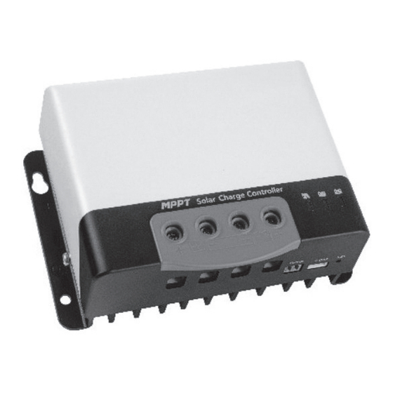
SAFETY INSTRUCTIONS 1. Please read the manual carefully before use and operate the controller only after safety operation training has been completed. 2. There are no parts inside the controller that need to be maintained or repaired. The user shall not disassemble and repair the controller. - Page 3 1 Solar panel interface (+) 8 PV charging indicator 2 Solar panel interface (-) 9 Battery level indicator 3 Battery interface (-) 10 Battery type indicator 4 Battery interface (+) 11 VCC12V/20mA 5 External temperature 12 RX sampling interface 13 TX 6 Communication Interface 14 GND 7 Operation keys...
- Page 4 CHARGING STAGE INTRODUCTIONS VP curve Battery voltage Fig. 2 VI curve P ( W ) As one of the charging stages, Quick charge Holding charge Floating charge MPPT cannot be used alone. It is Equalizing charge voltage Boost 94. 5 Boost charge voltage PPT point usually required to combine boost...
-
Page 5: Installation Precautions
INSTALLATION PRECAUTIONS Warning: Risk of explosion! • When installing a vented lead-acid battery, wear Equalising vented lead-acid protective glasses. If contact with battery acid, battery may generate explosive please rinse with clean water. gases. The battery compartment must be well ventilated. •... -
Page 6: Product Operation And Display
Step 1. Choose an installation location. Avoid installing the controller in a place free of direct sunlight, high temperature, and water, and ensure good ventilation around the controller. Step 2. Mark the position of the mounting holes. Drill 4 holes of the appropriate size. Fix screws into the upper two mounting holes. -
Page 7: Keys Operation
3. BATTERY TYPE INDICATOR KEYS OPERATION Colour Battery status There is a key on the controller, which is used in conjunction with the battery type indicator for Green Sealed lead-acid battery selection of battery type. The specific operation Yellow Colloidal lead-acid battery mode is as follows: Venated lead-acid battery In the current operating state, press and hold the key... - Page 8 COMPARISON OF PARAMETERS If a user-defined battery is used, the default voltage parameters of the system are the same as those of the sealed lead-acid battery: Overvoltage disconnection voltage> charge limit voltage ≥ equalizing charge voltage ≥ boost charge voltage ≥ floating charge voltage> boost charge recovery voltage;...
Need help?
Do you have a question about the MPPT Pro Plus and is the answer not in the manual?
Questions and answers