Table of Contents
Advertisement
Quick Links
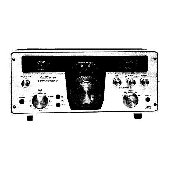
Allied AX/SX-190 Receiver
S
Ad for AX/SX-190 from Radio Shack catalog
S
Ad CQ Magazine, May 1972
S
73 Magazine Review
S
CQ Magazine Review, May 1972
S
NASWA Consumer Report, by Ed Shaw
S
QST Magazine Mods, by Paul Dujmich
S
CQ Magazine Mods, March 1973, by Bruce Mackey
S
Bandswitch Mods, by John Kolb
S
NASWA-FRENDX upgrading the SX-190, May 1974, by Ed Shaw
S
Comprehensive Technical Manual, by Ed Shaw
S
Miscellaneous Reviews and How-to's thru 1982
S
Allied Radio Shack Service Manual
S
Allied Radio Shack Instruction Manual
Resource Collection
Compliments of
Mark
Rehorst
Advertisement
Table of Contents

Related Manuals for Allied AX-190

Summary of Contents for Allied AX-190
- Page 1 CQ Magazine Mods, March 1973, by Bruce Mackey Bandswitch Mods, by John Kolb NASWA-FRENDX upgrading the SX-190, May 1974, by Ed Shaw Comprehensive Technical Manual, by Ed Shaw Miscellaneous Reviews and How-to’s thru 1982 Allied Radio Shack Service Manual Allied Radio Shack Instruction Manual...
- Page 4 The trick is finding the good receiver that is behind the AM with ANL are provided on the function switch. pretty panel. The Al lied AX-190 is such a one. Incidentally, the diode noise limiter performs very well Behind the brushed aluminum front are five printed to take out ignition and electrical noises (i.e..
- Page 5 Extremely sharp preselector tuning is had with image rejection on the AX-190 measured as 90, *Technical Director, CQ. 78, 74, 60, 50 db and i.f. signal rejection as 50, 70, 90, 105, 100 db on the 3.5, 7,14, 21 and 28 MHz...
- Page 6 The a.g.c. at- Bottom View of the AX-190. Lower part of the tack is exceptionally fast without any evidence of box for the v.f.o is at the center...
- Page 7 crystal oscillator, feeds an h.f.o.-output jack on the changed. The 455 kHz i.f. section has a passband rear of the set. of 4 kHz at 6 db down and since the b.f.o. crystals A 2920-2420 kHz amplifier precedes the second are only 3 kHz apart in frequency, the reinserted mixer.
- Page 8 The v.f.o. and variable-i.f. band- pass tuning circuits are in the box at the center. In the center fore- ground is a board with the a.f. sec- tion and power-supply compo- nents. At the right of the v.f.o. is the calibrator board. The r.f. circuit board is at the right with the h.f.o.
- Page 9 S.s.b. signals are easy to tune in and sound As noted earlier, with the AX-190 the one auxil- good in spite of the lower-than-usual unwanted- iary position is available for use in a 500 kHz sideband rejection capabilities of the receiver.
- Page 10 PUBLICATION Edward C. Shaw Acknowledgments: Mr. Paul Stanley, Allied Radio Shack, Fort Worth, Texas; Mr. Gene Welch, International Crystal Mfg. Co, Oklahoma City, Oklahoma; Mr. Al R. Niblack, North American SW Assn, Vincennes, Indiana. This publication is free of charge.
- Page 11 ALLIED SX-190 RECEIVER A Consumer’s Report by Edward C. Shaw The SX—190 receiver is a solid—state, crystal controlled short wave receiver with a dual—conversion circuit. This means that images are not likely to appear as in other single—conversion receivers. The circuitry provides reception of 11 short wave bands from 3.0 to 30.0 MHz.
- Page 12 Oklahoma City at a very reasonable price — at a 25% savings under Allied’s price. To labor on this point a bit, Allied nominally takes one or two months to provide crystals. Also, a half dozen known instances concerning Allied crystals revealed the wrong frequency when the crystals arrived.
- Page 13 The SX—190 comes equipped with some features found only on the most expensive receivers: or only available as an external additive. The built—in Q—multiplier and selectivity control is a marvel. Even without use of that control, stations are usually easily separated every 5 kHz, except the most stubborn cases involving very powerful or deliberately "splashy"...
- Page 14 OBSERVATIONS: The SX—190 is undoubtedly one of the prettiest machines ever devised. There are several minor annoyances or improvements, which the author has noted, and perhaps SX—190 owners might use their own ingenuity to make needed changes. The opaque plastic window should have been made from clear plastic in order to facilitate easier reading of the dials in daylight.
- Page 15 reading from your S—meter. The dial then descends 500 kHz in frequency to 8,840 kHz at 500 on your dial. Note that KOL Israel is then found at approximately 330 on your dial, which is really 9,009 kHz. Other crystals will produce similar out—of— band ranges —...
- Page 16 TV set in your for-lead compatible with with a printed circuit drill, The AX-190, as it was neighborhood. Now may- original transistors, one hole at Q2 and one at called, was a very respect- be you don’t care to hear...
- Page 17 Mackey describes modifi- less up to you. I used a tor. Peak up T1, T2, and tion stops and the prese- cations to the AX-190 agc piece of glass perf board T3 for maximum meter lector peaks up normally. circuit.
- Page 18 Fig. 3. Preamp circuit. Two RCA MOSFETs pro- vide an extra 20 dB gain when used ahead of the AX-190. Note that input and output's tuned circuits are actually a part of the receiver preselector on the if circuit board. Connections to them are made with No.
- Page 19 Modifying The Allied Radio Shack Series190 Receivers BY BRUCE L. MACKEY* For those who may have purchased the The audio selectivity of the Allied 190 Allied Radio Shack 190 receivers after receivers can be improved by removing C reading the excellent evaluation of these...
- Page 20 BY BRUCE L. MACKEY* Our first article in the March 1973 issue important, the sensitivity of the receiver. dealt largely with improving the Allied The final modification is designed to Radio Shack 190 series receivers with provide more control in the r.f. stage where regard to s.s.b.
- Page 21 10 MHz. This change is not reversible; once made, it cannot be undone, so you should be certain before you start exactly what you want. The AX-190 is the Ham Band version of the SX—190. The circuitry is similar, but it has even fewer bands below 10 MHz.
- Page 22 Refer to Figures 2 and 3 to see how the switch SW1 operates. This is a view of the preselector switch wafers from the rear of the receiver, with the bottom cover removed. Figure 2 is the switch position in the in the low band optional position.
- Page 23 WORK SHOP — Some useful guidance to upgrading of your SX—190 RECEIVER By far, one of the most popular receivers ever used in the SWL hobby is the Allied SX-190. Despite some of the problems in earlier receivers and the subsequent discontinuation of the model, the SX—l90 still remains one of the best values on the market, although only used re-...
- Page 24 NASWA — FRENDX MAY 1974 SX-190 WORKSHOP PART II by Ed Shaw Q-MULTIPLIER ALIGNMENT: We are now concerned with two small variable resistors on the right side of your receiver’s interior circuit board. These are identical components located imme- diately behind the S—meter. They appear as two side-by—side semicircles, in the illustration, as VR—15 and VR—16.
- Page 25 THE COMPREHENSIVE SX-190 MANUAL For Technician Owners By Ed C. Shaw I am the first to admit that Radio Shack’s first try was their best... they should have stuck to it. SX—190 and the amateur band sister AX—190 appeared on Radio shack’s shelves rather suddenly as I recall about the summer of ‘71, and at a price of $249.95, including a full complement of crystals covering most of the popular SWBC spectrum or all of the amateur bands.
- Page 26 A LIST OF OBSERVATIONS AND MODIFICATIONS To Install Additional Crystal Coverage Ta Change Crystal Calibrator To 5 KHz Verses 25 KHz III. To Change AGC Response Time - Or Adding-On A Switchable Option To Defeat AGC For Inverted Gain Control Technique Adding-On An Externa1 Switch For Dial Lights To Conserve Batteries Adding-On An Internal Speaker VII.
- Page 27 I. TO INSTALL ADDITIONAL CRYSTAL COVERAGE The owner invariably will want to fill up blank options with the most popular bands available. There seems to be no better choices than the 60-meter and 13-meter bands. Other choices, however, include the 90-meter or 11-meter bands or perhaps the amateur 20-meter or 15-meter bands.
- Page 28 Choose from this list the value, which most nearly fits your crystal require- ments. Be prepared to substitute one higher or lower in value if the first try doesn't work. Values shown are in standard picofarads (pF) 100, 120, 180, 220, 330, 390, 470, 560, 680, 820, 910, and 1000 pF.
- Page 31 TO CHANGE CRYSTAL CALIBRATOR TO 5 KHz VERSES 25 KHz The crystal calibrator employs a fixed crystal of 100 KHz in a simp1e oscil- lator to provide the 100 KHz markers, which is injected into the RF stage for us to hear. By pushing the 25 KHz marker button, a flip-flop circuit is acti- vated to divide the 100 KHz by 4...
- Page 32 TO DEFEAT AGC FOR INVERTED GAIN CONTROL TECHNIQUES Many DXers don’t even know about inverted gain control technique. This merely allows the operator to turn up the AF gain full and use the RF gain to con- trol volume. Many receivers will do this which have provision for manual gain control.
- Page 33 oval area to permit sound to pass thru the cover. Don’t forget to also drill holes for the screw holes for mounting the speaker. Underneath the chassis, examine the speaker jack (J7) on the rear panel. You will find three contacts. One goes to ground (chassis), one goes to the headphone jack, and the other has no wire attached.
- Page 34 selectivity skirt of the I.F., but provides about 3 dB extra gain. This is a modification which I normally would not recommend unless you need all the signal voltage you can get for DXing consistently weak catches having not much interference close by. X.
- Page 35 XII. A TRANSISTOR SUBSTITUTION GUIDE Device # GE sub ECG sub Function 2SK19 FET-2 Cascade RF Stage 2SC373 AGC Amp. 25K19 FET-2 Cascade RF Stage 2SK19 FET-2 1st Mixer 2SC371 289A 1st Local Osc. 2SCS71 289A 1st Local Osc. Emitter Follower 2SC372 1st IF Band Pass Amp.
- Page 36 In the same vicinity of the diodes, locate also touch-points #4 and #5. On the underside of the chassis, install a .00l/50V Mylar capacitor between touch-point pin #4 and #5. This may be too much reduction in RF for other normal bands;...
- Page 37 The 4.5 MHz position yields extra coverage of 4500 + 5840 = 1034O up to 10840. Remember though, it’s backwards. If you elect to purchase a 3.0 MHz crystal, it will yield 8.840 up to 9.340. The same theory works on the upper range positions as well.
- Page 40 XVIII. ADJUSTMENT OF 455 KHZ I.F. (ONLY IF NECESSARY) Examine the page (6) I.F. board drawing and locate MF-1 and MF-2 and T-9 and T-10. Remove antenna. Dial up a 100 mark, turn on calibrator, and adjust RF gain to halfway meter deflection. Turn on Q-multiplier to center the fre- quency in as best you can.
- Page 41 Another rudimentary tone control which might be tried is to put a 10K audio pot and a .05 uF capacitor in series, then wire it in between the Q-23 base and ground (touch-point #8). This would work for an amplifier with somewhat higher impedance input than the SX-190 amp has, so it might not be too effec- tive.
- Page 42 NASWA-FRENDX SWC-4 APRIL 1977 GETTING REACQUAINTED WITH THE SX-190 by EDWARD SHAW This is a receiver, which I got to know intimately. I have been inside and out of it for several years, making repairs, alterations, and experimental changes for entertainment. As one top NASWA DXer expressed it, "It (the SX- 190) is an experimenter’s delight!"...
- Page 43 NASWA — FRENDX SWC-5 APRIL 1977 GETTING REACQUAINTED WITH THE SX-l90 (Cont'd) There are some tricks to allow extra coverage. Each of the crystals in the SX-l90 can be deliberately mistuned in a higher range. For instance, the 3.5 MHz crystal provided with the SX-l90 nay be mistuned on the preselector for a range of frequencies between about 9,340 KHz and 8840 KHz.
- Page 44 condenser, which is tuned with a plastic screwdriver. Now we are ready to begin: 1. Receiver should be warmed up 30 minutes before starting work. 2. Connect your antenna. 3. Control settings: RF gain full clockwise; AF pain adjusted to com- fortable level;...
- Page 45 From "THIS & THAT" NASWA 7-80 Paul Kowolskl, 1557 N. Farwell Ave., Apt. 105, Milwaukee, WI 53202, writes to us regarding tuning the SX-190 receiver. As Most SX-190 owners probably know, the preselector can be mistimed to receive certain out of band frequencies. Ed Shaw, I believe, had an article on this some years ago.
- Page 46 Step 5: Solder the varicaps ground connection to the common ground shared by all the crystal capacitors. Solder the fixed plate connection to the crystal selector wafer switch inner contact ring. Step 6: If you succeeded in finding a true 900 pf variable capacitor, all in- dividual crystal capacitors may be removed.
- Page 47 I am the first to admit that Radio Shack’s first try was their best... they should have stuck to it. SX-190 and the amateur band sister AX-190 appeared on Radio Shack’s shelves rather suddenly as I recall about the summer of '71 and for $299.95, including the crystals.
- Page 48 ALLIED RADIO SHACK 3.5-30 MHz AM CW SSB COMMUNICATIONS RECEIVER MODEL AX - 190 CAT. NO. 20 - 5155 MODEL SX - 190 CAT. NO. 20 - 5190 SERVICE MANUAL A PRODUCT OF RADIO SHACK A TANDY CORPORATION COMPANY...
-
Page 49: Table Of Contents
CONTENTS General Specifications....................1 Disassembly Instructions.................... 2 Block Diagram ......................3 Alignment Procedure....................4 Location of each coils, transformers and trimers ............4 1) 455 KHz 2nd IF Amplifier..................4 2) 2.920 — 2.420 MHz 1st variable IF Amplifier ............. 5 3) VFO........................ -
Page 50: General Specifications
1. General Specification Number of semiconductor ......4FET, 22TR, 13 diode, 2 Zener and 2 thermister IF Frequency ..........2.920 to 2.420 MHz (Variable) and 455 KHz Reception..........AM, CW, and SSB Sensitivity (AM)........Less than 1 microvolt for 10 db S/N ratio Sensitivity (SSB) ........Less than 0.5 microvolt for 10db S/N ratio Selectivity..........4 KHz at 6 db down Visual dial accuracy .........±200 Hz Calibration accuracy.........Better than ±500 Hz adjacent 25 KHz... -
Page 51: Disassembly Instructions
Disassembly Instructions Remove all black screws then cabinet will be open. Fig. 1... -
Page 52: Block Diagram
BLOCK DIAGRAM Fig. 2... -
Page 53: Alignment Procedure
Alignment Procedure: 455 KHz 2nd IF Amplifier Method 1 (Using Sweep Generator) (1) Control Settings: RF Gain - Full Clockwise AF Gain - Max. Counterclockwise Band SW - Any band Function - AM Q-Multi - OFF - OFF Connect the Sweep Generator output to the hot side of the VC5, which is located in VFO Box. -
Page 54: 2) 2.920-2.420 Mhz 1St Variable If Amplifier
- Full clockwise AF Gain - Adjust for desired audio level Function - AM Band SW - Any band but recommend 27. 0 MHz for SX-190 or 29.5 MHz for AX-190 Preselector - Adjust to the selected frequency band Q-Multi - OFF (2) Rotate the main tuning knob to "0"... -
Page 55: 1St Local Crystal Oscillator (Hfo)
(4) Tune the main dial to 450 to the center tine. (5) Adjust the T7, in the VFO Box, to the exactly 2.925 MHz on the frequency counter. Repeat steps 2) thru 5) as necessary to obtain a frequency of 2.375 MHZ when the dial indicates "100"... -
Page 56: Preselector (Rf) Amplifier
32.420 MHz for AX-190 or 29.920 MHz for SX-190. Rotate the band SW to 29.0, 28.5, 28.0, 27, 21 and 15 MHz Band for AX-190 or 27.0, 17.5 and 15 MHz Band for SX-190 make sure that those frequency error are within 1 KHz. -
Page 57: 100 Khz Crystal Calibrator
(2) Connect the VTVM and 8 ohms dummy load to SPK jack. (3) Connect the signal generator to the antenna jack and adjust the frequency to 14 MHz. (4) Adjust L4, L5 and L6 on the RF PCB to maximum output. (5) Rotate the Band SW to 27 MHz Band, the preselector dial to just on marked "27"... -
Page 58: Reject And Select
7) Reject and Select Alignment (1) Control settings: RF Gain - Full clockwise AF Gain - Full counterclockwise Function - AM (2) Receive one of the calibration signals. (3) Q-multiplier SW to Reject position and set the tune knob to the center. (4) Adjust VR15 on the IF PCB to minimum reading on the S-meter. - Page 59 (2) Connect the VTVM and 8 ohms load to the SPK jack. (3) Connect the signal generator to the ANT jack and adjust the frequency to 2.920 MHz. (4) Adjust L1 to minimum reading on the VTVM. (5) Change the frequency of the signal generator to 3.500 MHz. (6) Adjust L3 to 3 dB decrease point on the VTVM.
- Page 60 -11-...
- Page 79 TECHNICAL SPECIFICATION Basic Frequency Coverage *Additional Band ............500 KHz band width *Crystal not supplied............3.5 to 10 MHz 80 meter Band ..............3.5 to 4.0 MHz 49 meter Band ..............5.7 to 6.2 MHz 40 meter Band (HAM) ............ 7.0 to 7.5 MHz 31 meter Band (WWV@ 10 MHz)........
- Page 80 GENERAL DESCRIPTION The SX-190 SHORTWAVE RECEIVER is fully transistorized and offers a new high in reliabil- ity, selectivity, and drift free operation. It covers the 49 thru 16-meter international broadcasting bands plus the 11-meter CB band and WWV at 10 and 15 MHz. Two blank positions are left for the owner who may by the addition of the proper crystal, cover any 500 KHz wide segment of frequency between 3.5 thru 10 MHz and 10.0 thru 30.0 MHz.
- Page 81 It is advisable to generally, look the receiver over and verify that nothing has been shaken loose and that everything appears to be normal. The following items are supplied with each receiver: 1. Instruction manual, ALLIED MODEL SX-190. 2. DC power cable assembly. 3. 1/4" phone plug connector.
- Page 82 1.2.3 GROUND CONNECTIONS and/or LIGHTNING ARRESTOR INSTALLATION A good external earth ground connection to the chassis is a must to eliminate a potential shock hazard. It is possible that a voltage may exist between the chassis and ground as a result of the power line bypass capacitor that is connected between chassis and the power line.
- Page 83 FIGURE 1-1 INTERCONNECTIONS A - Speaker jack G - AC line cord B - Line/Tape output H - Fuse C - VFO output I - HFO output D - Ext std-by J - GND terminal E - AC/DC switch K - 80-239 antenna jack F - DC input jack FIGURE 1-2 REAR VIEW OF SX-190...
- Page 84 FIGURE 1-3 ATTACHING CABLE TO PHONE PLUG CONNECTOR FIGURE 1-4 INSTALLATION OF GROUND...
- Page 85 ANTENNAS (a) Single Wire Antenna The single wire or inverted "L" type of antenna will provide satisfactory performance over the entire tuning range. Simply connect one end of the antenna wire to center pin of a PL-259 Con- nector and attach to Antenna Jack. For good reception the antenna wire should he 30 to 100 feet long and placed as high as possible (see Fig.
- Page 86 A - Power switch I - 25 kHz Calibrator switch B - Function switch J - 100 kHz Calibrator switch C - Band switch K - AF gain control D - Main tuning knob L - RF gain control E - Dial skirt M - "S"...
- Page 87 SECTION 2: CONTROLS AND THEIR FUNCTIONS Power Switch (A) Turns the set power on and off. Function Switch (B) This switch selects the mode of operation for the receiver. Each position selects the following mode: USB This position is used for CW (continuous wave or code) and upper SSB (Single side-band) operation.
- Page 88 CAL (I) (J) The calibrator circuit is crystal controlled and supplies 2 calibration frequencies. By pushing knob (I) to it's "in" position you activate the 25 kHz calibrator, which will provide marker signals every 25 KHz from 3.5 to 30.0 MHz. By pushing knob (J) to it's "in" position you activate the 100 KHz calibrator, which will provide marker signals every 100 KHz from 3.5 to 30.00 MHz.
- Page 89 OPERATING INSTRUCTIONS TABLE 1 CONTROL AM SETTING CW SETTING SSB SETTING Function AM or ANL USB or LSB USB or LSB AF Gain Adjust for desired Adjust for desired Adjust for desired audio level audio level audio level Band Sel Set for desired Set for desired Set for desired...
- Page 90 AM Operation For the reception of stations place all controls in the positions indicated in the Initial Control Set- tings chart. Tune in a station, using Main tuning controls as indicated in the section under "TUNING". Adjust Preselector for highest "S" meter reading. This control setting is satisfactory while operating over a limited frequency range.
- Page 91 TABLE 3 SHORTWAVE FREQUENCY (MHz) LISTENING TIME BROADCAST BAND* 49 meter band 5.95 to 6.20 Winter nights 41 meter band 7.10 to 7.30 Winter nights 31 meter band 9.50 to 9.775 Nights, all year 25 meter band 11.70 to 11.975 Nights, all year 19 meter band 15.10 to 15.45...
- Page 92 This control is used to set the dial skirt to exact center frequency of calibration signal. For first setting rotate tuning knob nearest to the 100 KHz maker signal until the tone is in the zero beat. Hold the tuning knob firmly at this point and rotate the dial skirt to zero position. The skirt dial is just behind the tuning knob and is held in position by a friction-locking device.
- Page 93 FIGURE 2-2 LOCATIONS OF EXTRA CRYSTAL AND CAPACITOR FIGURE 2-3 CHART OF EXTRA CRYSTAL FREQUENCY VS. CAPACITOR VALUE FOR 3.5 - 10 MHz RANGE FIGURE 2-4 CHART OF EXTRA CRYSTAL FREQUENCY VS. CAPACITOR VALUE FOR 10.0 - 30 MHz -15-...
- Page 94 -16-...
- Page 95 SECTION 3: THEORY OF OPERATION GENERAL This section will aid in understanding the operation of the various circuits in this receiver as well as an aid in servicing and diagnosing troubles. The SX-190 is a dual conversion receiver using a crystal-controlled oscillator to provide the first mixing.
- Page 96 FIRST MIXER AND BANDPASS IF The output of the RF Amplifier is applied to the gate of the first mixer Q4. At the same time the output of the HFO coupled thru T4 is applied to the source of the first mixer. The two signals are mixed and their products are selected in the drain circuit of Q4.
- Page 97 AUDIO CIRCUITS As stated earlier the audio voltage developed by a particular detector is coupled through the Function switch (SW3-d) to the AF Gain control (VR3). The audio voltage is amplified in three separate stages. The first audio amplifier Q23 feeds the second audio amplifier Q24 that drives the final audio output stage, which is operating push-pull, and consists of transistors Q25 and Q26.
- Page 98 REJECTION FILTER The Rejection Filter consists of transistors Q11, Q12 and their associated components. The fre- quency of the notch is controlled by VC7, REJECTION TUNING. This control allows the notch to be moved across the passband of the 455 KHz IF. Resistor, VR15, is used to adjust the depth of the notch.
- Page 99 SCHEMATIC DIAGRAM OF RF AMP -21-...
- Page 100 SCHEMATIC DIAGRAM OF BUFFER AMP SCHEMATIC DIAGRAM OF CALIBRATOR -22-...
- Page 101 SCHEMATIC DIAGRAM OF VFO SECTION -23-...
- Page 102 SCHEMATIC DIAGRAM OF I.F. AMP SECTION -24-...
- Page 103 SCHEMATIC DIAGRAM OF POWER SUPPLY -25-...
- Page 104 TRANSISTOR AND DIODE COMPLEMENT 2SK19 Cascode RE Stage 2SC373 AGC Amp. 2SK19 Cascode RF Stage 2SK19 1st Mixer 2SC371 1st Local Osc. 2SC371 1st Local Osc. Emitter Follower 2SC372 1St IF Band Pass Amp. 2SC784 2nd Mixer 2SK19 Variable Frequency Osc. 2SC372 Variable Frequency Osc.
- Page 105 1S188 Overload Protector 1S188 Overload Protector 7V Voltage Regulator 1S188 1S188 AM Detector 1S188 AGC Detector 1S188 AGC Detector 18188 Product Detector 18188 Product Detector 1S188 Product Detector 1S188 Product Detector FR-2 Rectifier FR-2 Rectifier ZB1-10 10V Voltage Regulator FR-2 Temperature Compensator TH 1 M-10K...
Need help?
Do you have a question about the AX-190 and is the answer not in the manual?
Questions and answers