Table of Contents
Advertisement
Advertisement
Table of Contents

Related Manuals for Allied SX-190

Summary of Contents for Allied SX-190
-
Page 2: Technical Specification
TECHNICAL SPECIFICATION Basic Frequency Coverage *Additional Band ............500 KHz band width *Crystal not supplied............3.5 to 10 MHz 80 meter Band ..............3.5 to 4.0 MHz 49 meter Band ..............5.7 to 6.2 MHz 40 meter Band (HAM) ............ 7.0 to 7.5 MHz 31 meter Band (WWV@ 10 MHz)........ -
Page 3: General Description
HFO and VFO outputs. Rugged mechanical construction plus modularized design provide for maximum mechanical sta- bility and ready access to either the top or bottom of the SX-190. This allows for maximum ease of maintenance or alignment should either become necessary. -
Page 4: Section 1: Installation
4. Additional feet. RECEIVER CONNECTIONS If the SX-190 Receiver is to be used for receiving only and not as part of a system with intercon- nections to an associated transmitter there are only a few required connections. These connec- tions are easily accessible at the rear of the receiver and their design permits permanent connec- tions to be made in a neat manner. - Page 5 The STD BY jack is jumpered in factory to operate the receiver. INTERCONNECTIONS FOR USE WITH TRANSMITTER Figure 1-1 (page 5) illustrates the interconnections required for using SX-190 Receiver with a transmitter. The following paragraphs describe the required interconnections to use the receiver in this man- ner.
- Page 6 B - Line/Tape output H - Fuse C - VFO output I - HFO output D - Ext std-by J - GND terminal E - AC/DC switch K - 80-239 antenna jack F - DC input jack FIGURE 1-2 REAR VIEW OF SX-190...
- Page 7 FIGURE 1-3 ATTACHING CABLE TO PHONE PLUG CONNECTOR FIGURE 1-4 INSTALLATION OF GROUND...
- Page 8 ANTENNAS (a) Single Wire Antenna The single wire or inverted "L" type of antenna will provide satisfactory performance over the entire tuning range. Simply connect one end of the antenna wire to center pin of a PL-259 Con- nector and attach to Antenna Jack. For good reception the antenna wire should he 30 to 100 feet long and placed as high as possible (see Fig.
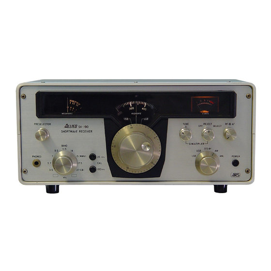
- Page 9 L - RF gain control E - Dial skirt M - "S" meter F - Main dial N - Q-multiplier switch G - Preselector O - Rejection tuning H - Preselector dial P - Phones jack FIGURE 2-1 FRONT VIEW OF SX-190...
-
Page 10: Section 2: Controls And Their Functions
SECTION 2: CONTROLS AND THEIR FUNCTIONS Power Switch (A) Turns the set power on and off. Function Switch (B) This switch selects the mode of operation for the receiver. Each position selects the following mode: USB This position is used for CW (continuous wave or code) and upper SSB (Single side-band) operation. - Page 11 CAL (I) (J) The calibrator circuit is crystal controlled and supplies 2 calibration frequencies. By pushing knob (I) to it's "in" position you activate the 25 kHz calibrator, which will provide marker signals every 25 KHz from 3.5 to 30.0 MHz. By pushing knob (J) to it's "in" position you activate the 100 KHz calibrator, which will provide marker signals every 100 KHz from 3.5 to 30.00 MHz.
- Page 12 OPERATING INSTRUCTIONS TABLE 1 CONTROL AM SETTING CW SETTING SSB SETTING Function AM or ANL USB or LSB USB or LSB AF Gain Adjust for desired Adjust for desired Adjust for desired audio level audio level audio level Band Sel Set for desired Set for desired Set for desired...
- Page 13 AM Operation For the reception of stations place all controls in the positions indicated in the Initial Control Set- tings chart. Tune in a station, using Main tuning controls as indicated in the section under "TUNING". Adjust Preselector for highest "S" meter reading. This control setting is satisfactory while operating over a limited frequency range.
- Page 14 TABLE 3 SHORTWAVE FREQUENCY (MHz) LISTENING TIME BROADCAST BAND* 49 meter band 5.95 to 6.20 Winter nights 41 meter band 7.10 to 7.30 Winter nights 31 meter band 9.50 to 9.775 Nights, all year 25 meter band 11.70 to 11.975 Nights, all year 19 meter band 15.10 to 15.45...
- Page 15 This control is used to set the dial skirt to exact center frequency of calibration signal. For first setting rotate tuning knob nearest to the 100 KHz maker signal until the tone is in the zero beat. Hold the tuning knob firmly at this point and rotate the dial skirt to zero position. The skirt dial is just behind the tuning knob and is held in position by a friction-locking device.
- Page 16 FIGURE 2-2 LOCATIONS OF EXTRA CRYSTAL AND CAPACITOR FIGURE 2-3 CHART OF EXTRA CRYSTAL FREQUENCY VS. CAPACITOR VALUE FOR 3.5 - 10 MHz RANGE FIGURE 2-4 CHART OF EXTRA CRYSTAL FREQUENCY VS. CAPACITOR VALUE FOR 10.0 - 30 MHz -15-...
- Page 17 -16-...
-
Page 18: Section 3: Theory Of Operation
This section will aid in understanding the operation of the various circuits in this receiver as well as an aid in servicing and diagnosing troubles. The SX-190 is a dual conversion receiver using a crystal-controlled oscillator to provide the first mixing. The first and second mixers are coupled by a band-pass IF circuit 500 kHz wide. - Page 19 FIRST MIXER AND BANDPASS IF The output of the RF Amplifier is applied to the gate of the first mixer Q4. At the same time the output of the HFO coupled thru T4 is applied to the source of the first mixer. The two signals are mixed and their products are selected in the drain circuit of Q4.
-
Page 20: Audio Circuits
AUDIO CIRCUITS As stated earlier the audio voltage developed by a particular detector is coupled through the Function switch (SW3-d) to the AF Gain control (VR3). The audio voltage is amplified in three separate stages. The first audio amplifier Q23 feeds the second audio amplifier Q24 that drives the final audio output stage, which is operating push-pull, and consists of transistors Q25 and Q26. -
Page 21: Ac Power Supply
C80. 3.11 POWER SUPPLY The power supply of the SX-190 has the advantage of operating from 120 VAC 60 Hertz or 12 VDC without any internal wiring changes. 3.11.1 AC POWER SUPPLY Transformer T13 steps down the voltage from the source to a nominal voltage of approximately 10 Volts. - Page 22 SCHEMATIC DIAGRAM OF RF AMP -21-...
- Page 23 SCHEMATIC DIAGRAM OF BUFFER AMP SCHEMATIC DIAGRAM OF CALIBRATOR -22-...
- Page 24 SCHEMATIC DIAGRAM OF VFO SECTION -23-...
- Page 25 SCHEMATIC DIAGRAM OF I.F. AMP SECTION -24-...
- Page 26 SCHEMATIC DIAGRAM OF POWER SUPPLY -25-...
- Page 27 TRANSISTOR AND DIODE COMPLEMENT 2SK19 Cascode RE Stage 2SC373 AGC Amp. 2SK19 Cascode RF Stage 2SK19 1st Mixer 2SC371 1st Local Osc. 2SC371 1st Local Osc. Emitter Follower 2SC372 1St IF Band Pass Amp. 2SC784 2nd Mixer 2SK19 Variable Frequency Osc. 2SC372 Variable Frequency Osc.
- Page 28 1S188 Overload Protector 1S188 Overload Protector 7V Voltage Regulator 1S188 1S188 AM Detector 1S188 AGC Detector 1S188 AGC Detector 18188 Product Detector 18188 Product Detector 1S188 Product Detector 1S188 Product Detector FR-2 Rectifier FR-2 Rectifier ZB1-10 10V Voltage Regulator FR-2 Temperature Compensator TH 1 M-10K...
Need help?
Do you have a question about the SX-190 and is the answer not in the manual?
Questions and answers