
Related Manuals for CMR Electrical LD4-2


Summary of Contents for CMR Electrical LD4-2
- Page 1 CMR Electrical Ltd Bolton House Five Chimneys Lane Hadlow Down East Sussex TN22 4DX Tel: 01825 733600 LD4-2 & LD4-2V 3 and 4 Zone Water Detection Alarm Installation and Operation Manual...
-
Page 2: Table Of Contents
Contents Display and Control Operation Water leak detected Alarm Test Water Detected Alarm Sensor Fault Water Detection Sensitivity Adjustment Installation Positioning the water detection cable Fitting Cable clips Water Shutdown Valve Water Shutdown Valve Override Procedure Beacon and beacon sounder Fitting an SMS /Email messaging system Fitting the battery backup Commissioning... -
Page 3: Display And Control
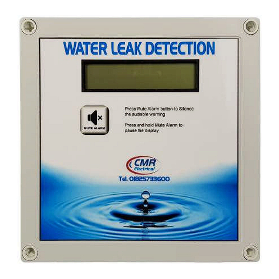
1) Display and Control Zone Status Display Mute Alarm Push Button Valve Shutdown Override Button Zone Sensitivity Removable Terminal Block Adjustment see for connection to the water Item 6 below detection cable or sensor Display Screens All detection cables or sensors are connected correctly and a water leak has not detected The detection cable or sensor has been disconnected, unplugged, damaged or cut A water leak has been detected in the detection cable or sensor... -
Page 4: Operation
2) Operation In normal operation with no alarms or faults, the audible warning device will be OFF and the display will be showing “The System has no Alarms or Faults”. If one or more of the zones has a disconnected or damaged cable, the audible warning device will sound and the display will show “... -
Page 5: Installation
7) Installation THIS EQUIPMENT SHOULD ONLY BE CONNECTED AND WORKED ON BY A QUALIFIED ELECTRICIAN. To mount the unit to a wall, first remove the front cover to expose the internal equipment. In each corner of the housing positioned below/above the front cover fixings will be found the mounting holes. Plastic glands have been provided for incoming power and outgoing signal cables. -
Page 6: Positioning The Water Detection Cable
Connection of the Signal cable, Water detection cable & End Of Line Terminator Signal cable, maximum 50 Water leak metres long, to detection Cable Water detection run around the cable connectors area to be protected Terminate the Red and Black wires to End of line the terminals within Terminators... -
Page 7: Water Shutdown Valve
10) Water Shutdown Valve If the system is supplied with water shutoff valves, once a water leak has been detected the unit will remove the 230V supply holding open the valve thereby closing it and stopping the flow of water. Once the leak has been rectified the detection cable may take some hours to dry out. -
Page 8: Water Shutdown Valve Override Procedure
11) Water Shutdown Valve Override Procedure This future will only work if there is a current water leak detected alarm, the zone has not already been overridden and the alarm has been Muted. To put the system into shutdown override and re-open the water valve, press and keep pressed the “Shutdown Override”... -
Page 9: Fitting An Sms /Email Messaging System
Warning; if the above option “12c” is required, remove the electrical link connected between the second (Strobe -) & third terminals (Tone -) terminals within the sounder. 13) Fitting an SMS / Email messaging system Use the “Text” terminal block LD4-2 Cable wire colours fitted Terminal No. to the messaging system BLUE... - Page 10 17 Fault Diagnoses Fault Possible Reason Display is OFF and the unit appears dead 1) No power to the control unit. Test with a meter 2) The power fuse has blown. Test the fuse with a meter The Water Detected statement remains in the 1) The cable needs drying out after detecting water.
- Page 11 18 Installation Drawings System using Water Detection Cable. Not all the shown devises may be available on your system...
- Page 12 19 Housing Sizes Main control unit and Outstation type OS4V...
Need help?
Do you have a question about the LD4-2 and is the answer not in the manual?
Questions and answers