
Related Manuals for CMR Electrical LD8-2


Summary of Contents for CMR Electrical LD8-2
- Page 1 CMR Electrical Ltd Bolton House Five Chimneys Lane Hadlow Down East Sussex TN22 4DX Tel: 01825 733600 LD8-2 & LD8-2V 6 & 8 Zone Water Detection Alarm Installation and Operation Manual...
-
Page 2: Table Of Contents
Contents Display and Control Operation Water leak detected Alarm Test Water Detected Alarm Sensor Fault Water Detection Sensitivity Adjustment Installation Positioning the water detection cable Fitting Cable clips Water Shutdown Valve Water Shutdown Valve Override Procedure Beacon and beacon sounder Fitting the battery backup Commissioning Fault Diagnosis... -
Page 3: Display And Control
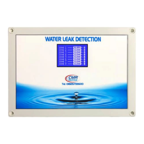
1) Display and Control Valve Shutdown Override Button Zone Test Button Touch Screen and Zone Status Display Removable Terminal Block Zone Sensitivity for connection to the water Adjustment see detection cable or sensor Item 6 below Display Screens a) All detection cables and or sensors are connected correctly and free from any water leaks Touch the screen and the display will change to the following for 5 seconds... -
Page 4: Operation
b) The detection cable or sensor has been disconnected, unplugged, damaged or cut After pressing the “Mute Alarm” the display will change to c) A water leak has been detected in the detection cable or sensor After pressing the “Mute Alarm” the display will change to 2) Operation In normal operation with no alarms or faults, the audible warning device will be OFF and the display will be showing (a) above. -
Page 5: Water Leak Detected Alarm Test
If water shutoff valves are fitted, and a zone detects water, the appropriate valve will close and the appropriate internal “Closed” lamp will illuminate. The system will automatically open the valve allowing water to flow once more providing the “Mute” button has been operated to acknowledge the alarm, the water leak has been cleared up and the detection cabled dried out. -
Page 6: Installation
7) Installation THIS EQUIPMENT SHOULD ONLY BE CONNECTED AND WORKED ON BY A QUALIFIED ELECTRICIAN. To mount the unit to a wall, first remove the front cover to expose the internal equipment. In each corner of the housing positioned below/above the front cover fixings will be found the mounting holes. Care should be taken when drilling the holes to ensure no damage occurs to the electronic equipment. -
Page 7: Positioning The Water Detection Cable
Connection of the Signal cable, Water detection cable & End Of Line Terminator Signal cable to Water detection Water leak cable connectors detection Cable run around the area to be protected Terminate the Red and Black wires to End of line the terminals within Terminators The alarm housing... -
Page 8: Water Shutdown Valve
10) Water Shutdown Valve If the system is supplied with water shutoff valves, once a water leak has been detected the unit will remove the 230V supply holding open the valve thereby closing it and stopping the flow of water. Once the leak has been rectified the detection cable may take some hours to dry out. -
Page 9: Water Shutdown Valve Override Procedure
11) Water Shutdown Valve Override Procedure This future will only work if there is a current water leak detected alarm, the zone has not already been overridden and the alarm has been Muted. To put the system into shutdown override and re-open the water valve, press and keep pressed the “Shutdown Override”... -
Page 10: Fitting The Battery Backup
13) Fitting the battery backup The battery should be fitted connected after the system as been commissioned. Place the battery within the housing in the space provided. Connect the small BLACK cable to the “—“ battery terminal and the RED with black dots wire to the batteries “+” terminal. If the battery is misconnected, the battery fuse located on the small PCB will blow. - Page 11 16) Installation Drawings Alarm Alarm Alarm Alarm System using Water Detection Cable. Not all the shown devises may be available on your system...
Need help?
Do you have a question about the LD8-2 and is the answer not in the manual?
Questions and answers