Table of Contents
Advertisement
Quick Links
TECHNICAL SUPPORT: 1-800-403-3279
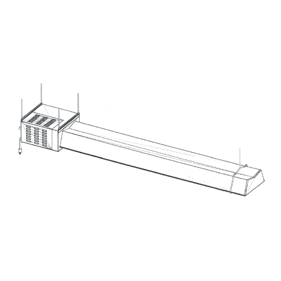
Infrared Radiant Tube Heater/Radiateur a tube rayonnant a infrafouge
A COPY OF THIS MANUAL MUST BE PROVIDED TO THE END USER
The installation must conform with local building codes or, in the absence of local
codes, the National Fuel Gas Code, ANSI Z223.1/NFPA 54, or the Natural Gas and
Propane Installation Code, CSA B149.1 The latest edition Electrical Code PART 1
CSA C22.1 in Canada and ANSI/NFPA NO 70 in the USA must also be observed.
It is beyond the scope of these instructions to consider all conditions that may be encountered
WARNING: Improper installation,
adjustment, alteration, service or
maintenance can cause property
damage, injury or death. Read the
installation, operating and maintenance
instructions thoroughly before installing
or servicing this heater.
Installation / Operating Instructions for
Easy Radiant "Works"
HEATWAVE
MODEL NUMBERS
GH40N
40,000 BTUH
LIQUID PROPANE OR NATURAL GAS
GH40P
AVERTISSEMENT. Une installation, un
réglage, une modification, une réparation ou
un entretien incorrect peut entraîner des
dommages matériels, des blessures ou la
mort. Li sez attentivement les instructions
d'installation, de fonctionnement et d'entretien
avant
de
procéder
àl'entretien de cet radiateur.
à
l'installation
.
ou
1
Advertisement
Table of Contents

Related Manuals for Easy Radiant Works HEATWAVE GH40N

Summary of Contents for Easy Radiant Works HEATWAVE GH40N
- Page 1 TECHNICAL SUPPORT: 1-800-403-3279 Installation / Operating Instructions for Easy Radiant “Works” HEATWAVE Infrared Radiant Tube Heater/Radiateur a tube rayonnant a infrafouge A COPY OF THIS MANUAL MUST BE PROVIDED TO THE END USER MODEL NUMBERS GH40N GH40P 40,000 BTUH LIQUID PROPANE OR NATURAL GAS The installation must conform with local building codes or, in the absence of local codes, the National Fuel Gas Code, ANSI Z223.1/NFPA 54, or the Natural Gas and Propane Installation Code, CSA B149.1 The latest edition Electrical Code PART 1...
-
Page 2: Appliance Overview
APPLIANCE OVERVIEW The Heatwave Shop/Garage heater is supplied with a region specific ½” flexible gas connector, a 24V thermostat, 5’ of 5” dia. direct vent, and a side wall vent termination cap. Please verify that these components are accounted for against the including factory packing list. -
Page 3: Safety Alert
WARNING THIS AND EVERY GAS FIRED PRODUCT MUST ONLY BE INSTALLED OR SERVICED BY A PROFESSIONALLY LICENSED AND QUALIFIED GAS TECHNICIAN. INSTALLING GAS FIRED APPLIANCES WITHOUT THE REQUISITE LISCENCE, KNOWLEDGE AND/OR UNDERSTANDING OF ALL RELEVELANT CODES AND REQUIREMENTS CAN RESULT IN FIRE, EXPLOSION, PROPERTY DAMAGE, INJURY, DEATH, BE CONSTRUED AS NEGLIGENCE, AND/OR CAUSE THE CANCELLATION OF IN FORCE LOSS/LIABILITY INSURANCE COVERAGE. - Page 4 WARNING ATTENTION This appliance may have sharp edges and Cet appareil peut avoir des arêtes vives et des corners. Wear protective clothing such as gloves coins. Porter des vêtements de protection tels and protective eye wear when servicing this or que des gants et des lunettes de protection lors any other appliance de l'entretien de cet appareil ou de tout autre...
-
Page 5: Clearances To Combustibles
CLEARANCES TO COMBUSTIBLES Clearances to Top (Above Back (Back of Sides Below Below (Reflectors combustibles Reflector) angled (Reflectors flat) angled) reflector) All Models 4” (10 cm) 4” (10 cm) 18” (46 cm) 36” (92 cm) 30” (76 cm) 60.9 cm ’... - Page 6 CLEARANCES TO COMBUSTIBLES (CONT.) In locations used for the storage of combustible materials, signs must be posted to specify the maximum permissible stacking height to maintain the required clearances from the heater to the combustibles, and that such signs must either be posted adjacent to the heater thermostats or in the absence of such thermostats in a conspicuous location.
- Page 7 SERVICE TECHNICIAN ONLY. READ AND UNDERSTAND THESE INSTRUCTIONS THOROUGHLY BEFORE ATTEMPTING TO INSTALL, OPERATE OR SERVICE THE EASY RADIANT WORKS HEATER. FAILURE TO COMPLY WITH THESE WARNINGS AND INSTRUCTIONS, AND THOSE ON THE HEATER COULD RESULT IN PERSONAL INJURY, DEATH, FIRE, ASPHYXIATION, AND / OR PROPERTY DAMAGE.
- Page 8 APPLICATION This gas fired radiant tube heater may be installed for heating of workshop / garages / commercial / industrial / agricultural non-residential domicile type spaces. It is beyond the scope of these instructions to consider all conditions that may be encountered. Installation must conform with all local building codes or, in the absence of local codes, to the National Fuel Gas Code, ANSI Z223.1/NFPA54 in the U.S.A.
-
Page 9: Gas Connection
WARNING FLAMMABLE/EXPLOSIVE/CORROSIVE VAPORS Where there is the possibility of exposure to combustible airborne materials or vapour, consult the local fire inspector's office, the fire insurance carrier or other applicable authorities for approval of the proposed installation. Do not use in an atmosphere containing halogenated hydrocarbons or other corrosive chemicals. - Page 10 WARNING VENTING Inadequate venting of a heater may result in asphyxiation, carbon monoxide poisoning, injury or death. The heater may be directly or indirectly vented from the space. Venting must be in accordance with all local, state, provincial, and national codes (ANSI Z223.1/NFPA 54 in USA;...
- Page 11 INSTALLATION IN COMMERCIAL AIRCRAFT HANGARS (CONT.) Heaters must be located where they are protected from damage to aircraft and other objects, such as cranes and movable scaffolding. Heaters must be located so as to be accessible for servicing and adjustment. INSTALLATION IN COMMERCIAL GARAGES AND PARKING STRUCTURES Low intensity heaters are suitable for use in commercial garages when installed in...
-
Page 12: Appliance Installation
GENERAL INSTALLATION PROCEDURE PRE-INSTALLATION SURVEY It is recommended that a full heating design, including a heat loss calculation be conducted. Heater sizing and placement must consider available mounting height, sources of heat loss, and clearances to combustibles with respect to stored material, moveable objects (cranes, vehicles, lifts, overhead doors, etc) sprinkler systems, and other obstructions on the site. - Page 13 APPLIANCE INSTALLATION (CONT.) HORIZONTAL INSTALLATION While the appliance is on the floor, attach four equal lengths of #10 jack chain (or equivalent) to the 4 holes in the fixed hangers on the burner box with field supplied “S” hooks. Attach length of #10 jack chain (or equivalent) to the center suspension point on the adjustable hanger located on the tube/reflector section of the appliance with field supplied “S”...
- Page 14 APPLIANCE INSTALLATION (CONT.) Once appliance is securely suspended from the structure, verify all required clearances and dimensions are correct. Connect the burner to the gas supply using a suitably approved flexible gas connector as outlined in this manual. Install exhaust/intake air venting as outlined in this manual. Install thermostat control wiring as outlined in this manual.
-
Page 15: Suspending The System
SUSPENDING THE SYSTEM WARNING Inadequate or improper suspension of the tube heater can result in collapse of the system, property damage, risk of fire/explosion, personal injury and/or death. It is the installer’s responsibility to ensure that the hardware and structural supports from which the heater is suspended are sound and of adequate strength to support the weight and expansion forces of the heater. -
Page 16: Electrical Requirements
ELECTRICAL/CONTROLS ELECTRICAL REQUIREMENTS 120VAC / 60 Hz / Single Phase / 1A / 3 Wire Grounded Starting Current: 3 amps Running Current: 1 amp 1. Electrical installation must be grounded in accordance with CSA Standard C22.1 part 1 in Canada or The National Electrical code ANSI NFPA 70 (latest edition) in the United States. -
Page 17: Gas Supply Piping
GAS SUPPLY PIPING 1. All gas piping and connections shall be made in accordance with all applicable local codes and the latest versions of CAN/CGA B-149 or ANSI standard Z223.1. 2. Connect the burner to gas supply with flexible gas connector. 3. - Page 18 WARNING Never use a match or other flame to test for gas leaks. Use soap and water solution to check for leaks to all connections and joints and if bubbles appear, leaks have been detected and must be corrected. Never operate an appliance with leaking fuel supply system.
- Page 19 WARNING HEATER EXPANSION Consider that the heater will expand in length as much as ½ inch (12.5 mm) or more for every 10 ft (3 m) of system length. In general, the greater the appliance firing rate, the greater the rate of expansion. This heater will expand in length as it heats up.
-
Page 20: Venting Requirements
The Heatwave heater MUST be installed with the venting system supplied with the heater, or one of the optional venting kits available from Easy Radiant Works. DO NOT connect the heater to a separate chimney and DO NOT common vent with any other fuel-burning appliance. -
Page 21: Vent Installation
VENT INSTALLATION After the heater has been properly suspended according to this manual, proceed to install the venting as described below: Measure the distance from the floor to the center of the vent collar on the rear of the burner. Transfer this measurement to the inside surface of the exterior wall that the vent will penetrate, and make a mark. - Page 22 VENT INSTALLATION WITH 90 DEGREE ELBOW INSTALLING HORIZONTAL VENTING WITH AN ELBOW After the heater has been properly suspended in accordance with this manual, proceed to install the venting and 90-degree elbow as described below. Note: a 90-degree elbow kit (available from the manufacturer, part # GH-110) is required for this installation.
- Page 23 VENT INSTALLATION WITH 90 DEGREE ELBOW (CONT.) Attach the 3" (7.6 cm) elbow portion of the 90-degree elbow kit to the 3" (7.6 cm) flue pipe (length A). Use high temperature RTV type silicone and 3 sheet metal screws installed at 120 degree intervals around the diameter of the material.
- Page 24 EXHAUST VENT TERMINATION SPECIFICATIONS Clearances from the exhaust vent termination are determined by local or national codes, but must not be less than 6” (15 cm.) from any combustible materials. All building materials must be adequately protected from potential degradation by flue gases.
-
Page 25: Bird Screen Installation
BIRD SCREEN INSTALLATION The bird screen is supplied in order to prevent blockage of the flue vent by birds or other small animals nesting in the flue. It must be installed directly at the end of the 3” (7.6 cm) flue. Orient the bird screen so that the flat surface is toward the exterior. - Page 26 TECHNICAL INFORMATION & TROUBLESHOOTING FIELD CONVERTING APPLIANCES CAUTION EFORE PROCEEDING WITH THE CONVERSION THE APPLIANCE GAS SUPPLY SHALL BE SHUT OFF PRIOR TO DISCONNECTING THE APPLIANCE ELECTRICAL POWER ATTENTION: AVANT DE PROCÉDER À LA CONVERSION, COUPER L'ALIMENTATION EN GAZ PUIS COUPER L'ALIMENTATION ÉLECTRIQUE.
- Page 27 FIELD CONVERTING APPLIANCES (CONT.) NATURAL GAS AND LIQUID PROPANE CONVERSION INSTRUCTIONS: Note: The maximum certified input for any GH series heater is 40,000 BTUH. A field conversion kit is available from natural gas to propane or propane to natural gas. Model no., serial no.
- Page 28 NATURAL GAS AND LIQUID PROPANE CONVERSION INSTRUCTIONS (CONT.) Read the instructions supplied with the conversion kit for details unique to the associated valve carefully. Failure to follow instructions provided with the conversion kit can damage product or cause a hazardous condition, property damage, personal injury or loss of life.
-
Page 29: Troubleshooting
TROUBLESHOOTING WARNING Improper adjustment, alteration, service or maintenance can cause property damage, injury or death. This heater must be installed and serviced only by a trained gas service technician. If at the onset of ignition, no ignition occurs, the following should be checked. ... -
Page 30: Recommended Maintenance
RECOMMENDED MAINTENANCE WARNING Improper adjustment, alteration, service or maintenance can cause property damage, injury or death. This heater must be installed and serviced only by a trained gas service technician. Carry out these steps at a minimum prior to every heating season. It is recommended that they be conducted routinely throughout the heating season as well. - Page 31 WARRANTY ALL Easy Radiant Works heaters are covered by a 4 year guarantee. All heaters manufactured by Easy Radiant Works are warranted to the original user against defects in materials and workmanship under normal use for a period of 4 years from date of purchase.
- Page 32 START-UP/TECHNICAL SUPPORT INFORMATION This equipment has been factory fired and tested prior to shipment. To ensure that site conditions are compatible with the heater’s performance, the following start up needs to be completed by the qualified gas installer. A technician calling for technical support must provide the information from the following completed reports.
- Page 33 IS THERE A BAFFLE INSTALLED IN THE RADIANT TUBE IF REQUIRED..WHAT IS THE LENGTH OF THE BAFFLE(S ) FEET IF INSTALLED..IS THE BAFFLE AT FLUE END OF SYSTEM THIS HEATER MUST BE ELECTRICALLY GROUNDED TECHNICAL SUPPORT: FAX 905-899-2262, VOICE 905-899-3473 EASY RADIANT WORKS...
- Page 34 SV95 SERIES HONEYWELL SMART VALVE...
- Page 35 HONEYWELL SMARTVALVE LED STATUS INDICATES CHECK/REPAIR No power to system control. 1. Line voltage input power at L1 and L2 connectors on Terminal Board. 2. Low voltage (24V) power at 24VAC and COM terminals on Terminal Board. 3. System wiring harness in good condition and securely connected at both ends.
- Page 36 AB2017 H.S.I. CONTROL MODULE...
- Page 37 AB2017 CONNECTOR GUIDE 1 2 3 4 8 Pin Molded Connector 5 6 7 8 for C1 4 Pin Molded Connector 13 14 for C3 16 15 LED Code Indicator 4 Pin Molded Connector for C2 3 Pin Molded Connector for C4 PIN 1 Loop to Pin 5...
- Page 38 AB2017 TROUBLE SHOOTING LED STATUS INDICATES CHECK/REPAIR No power to system control. 1. Line voltage input connectors on module. 2. Low voltage 24V and COM connection on module. 3. System wiring harness in good condition and securely connected at both ends. 4.
- Page 40 OMBUSTIBLE MATERIAL STORAGE WARNING SIGN...
Need help?
Do you have a question about the HEATWAVE GH40N and is the answer not in the manual?
Questions and answers