Table of Contents
Advertisement
Quick Links
MODEL TCR-109-41/42
OPERATION, SERVICE AND PARTS MANUAL
ROAD TANKER AND ISO TANK CONTAINER REFRIGERATION UNIT
Address: 4075 East Market Street York, PA 17402-5100 USA
Telephone: 717-840-4500
Telefax: 717-840-4501
www.klingecorp.com
MANUFACTURED BY KLINGE CORPORATION
UNCONTROLLED WHEN PRINTED
K35-TCR109-41/42
Rev. K, July 2023
Advertisement
Table of Contents

Related Manuals for KLINGE TCR-109-41

Summary of Contents for KLINGE TCR-109-41
- Page 1 MODEL TCR-109-41/42 OPERATION, SERVICE AND PARTS MANUAL ROAD TANKER AND ISO TANK CONTAINER REFRIGERATION UNIT Address: 4075 East Market Street York, PA 17402-5100 USA Telephone: 717-840-4500 Telefax: 717-840-4501 www.klingecorp.com MANUFACTURED BY KLINGE CORPORATION UNCONTROLLED WHEN PRINTED K35-TCR109-41/42 Rev. K, July 2023...
- Page 2 UNCONTROLLED WHEN PRINTED K35-TCR109-41/42 Rev. K, July 2023...
- Page 3 REVISION RECORD Description Date Approved Added TCR-109-42, refrigerant R-452A 6/3/2019 Corrected Section 7.6A illustration 11/13/2019 Updated Dual System Electrical 12/5/2019 Schematics Revised Section 7.6B, Item 1, was 64 FT, added file name and revision to 3/23/2020 footer of all sheets. Added Expansion Tanks to Section 7, and various updates based on full 2020/08/21...
- Page 4 Service Request Requests for Service should be directed to the Klinge Service Team. The below link should be used to place all requests for service and will afford the quickest response time. https://klingecorp.com/request-service/ This form will help us determine model and age of the equipment, location, basic details about the issue, who to contact and how to best handle the issues with the equipment.
- Page 5 This is available on the appropriate safety data sheet. Klinge can fax or email you the latest revision of the US/Canadian Material Safety Data Sheet or your local Dow Chemical sales and technical support office can send you a copy of the same data particular to your location, language, custom and legislation.
-
Page 6: Table Of Contents
3.7 Opening the System or Unbrazing Components ................. 23 3.8 Heat Transfer Fluid Circulating System ..................23 3.9 Hi-Pot Testing ..........................24 3.10 General Description Klinge Corporation Thermostat .............. 25 SECTION FOUR - TROUBLESHOOTING ................28 4.1 General Information ........................28 ... - Page 7 5.2 Air Trap and Vent .......................... 37 5.3 Filling the Heat Transfer Fluid System ..................37 5.4 The Expansion Tank Charge ......................39 5.5 The Pump ............................39 5.6 Air Blockage ............................ 39 5.7 Charging Steps Checklist for a Closed Pressurized System ............40 5.8 Filling the Glycol Pressure System and Venting the Air ............
-
Page 8: Section One - General Description, Installation, Operation
SECTION ONE - GENERAL DESCRIPTION, INSTALLATION, OPERATION 1.0 Nomenclature The TCR-109 is specifically designed to fit the bottom side rail of beam and frame tanks. The last two digits record the “as built” details. As ISO convention dictates, we label the rear of the tank container as the end with the discharge valves. -
Page 9: Circulating Pump Assembly
allows the compressor to produce lower temperatures for the cargo without adding additional weight. 1.3 Circulating Pump Assembly The circulating pump assembly is a close-coupled centrifugal pump and motor. The circulating pump assembly is low maintenance with sealed bearings supporting the motor and the fluid being pumped through it provides lubrication for the pump. -
Page 10: Connecting Tcr-109 To The Tank Cooling System
The unit has two holes fitted with M10 X 1.5 nut inserts, on each end, adjacent to the bottom rail cutout. These are to be used in conjunction with a simple angle to attach the unit to the beam. The rear of the unit can have additional threaded holes. The rear of the unit requires some support to resist the turning moment, as the unit will want to rotate about the bottom rail. -
Page 11: The Expansion Tank System
This is equivalent to the expansion tank found next to the radiator in most modern cars. Klinge Corporation can supply a bolt-on tank or the builder can fabricate it as part of the tank frame. It is basically very simple, and we suggest the builder fabricate and install it rather than have to integrate a U.S. -
Page 12: Installation Checkout Procedure
On initial filling, air tends to be trapped in this area and should be vented. Klinge Corporation can supply the vents, but we need to look to the installer to provide the pipes through the insulation. Without final details of the heating coils it is impractical to suggest how many vents are required. - Page 13 3. Open the electrical control box and inspect it to ensure that all connections are tight and electrical components are secured properly. Check that the door gaskets seal properly. 1.9.2 Starting the TCR-109 Connect the main power plug into a receptacle rated at 480V AC to supply power to the unit. Check to ensure that CB1, CB2, and CB3 are in the "ON"...
- Page 14 some liquids. This is particularly true when the carriage temperature is near the freezing point of the cargo. The heat transfer fluid limit temperature prevents this. See Section 1.9.5. Creating a temperature set point: 1. Pressing the UP () or DOWN () key causes the display to show the current set point. 2.
- Page 15 9. Once the third digit has been entered press the C/F key to confirm the PIN CODE that you have entered. 10. If the PIN Code that has been entered is not correct the Temperature Display will read “Pin”. 11. If the code that has been entered is correct the Temperature Display will show the Return Air Temperature.
- Page 16 PROBE RESISTANCE CHART Probe at Ambient K-Ohms Temperature (Approx.) + 25 10.0 + 20 12.4 + 15 15.7 + 10 19.9 25.3 32.6 42.6 - 10 55.3 - 15 72.9 - 20 97.0 - 25 130.3 1.9.5 Setting the Upper and Lower Limit for Heat Transfer Fluid The function of this setting is to limit “local under cooling”...
-
Page 17: Section Two - Detailed Functional Description
SECTION TWO - DETAILED FUNCTIONAL DESCRIPTION 2.1 Refrigeration System Operation The TCR-l09 refrigeration system is uncomplicated, easy to operate, and requires very little maintenance. Central in the TCR-109 is the scroll compressor, which represents the next generation in refrigeration technology and has several advantages over more conventional compressor styles. -
Page 18: Heat Transfer Fluid) Circulating System Operation
2.1.1 Liquid Injection System The low temperature operation of the TCR-109, down to -40°C (-40°F), requires that a liquid injection system be used to aid in controlling the compressor temperature. The advantage of this system is that it tends to be self-regulating. As pressure increases in the scroll, the demand for liquid injection increases. - Page 19 The DTC valve monitors the flow of liquid refrigerant into the injection port, based on the temperature of the thermal element located in the top cap thermal well of the compressor. The scroll compressor is also equipped with an internal pressure relief (IPR) valve, which opens when the differential pressure from suction to outlet reaches an unacceptable limit.
-
Page 20: Section Three - General Maintenance Requirements
SECTION THREE - GENERAL MAINTENANCE REQUIREMENTS 3.1 Pre-Trip Maintenance Pre-trip maintenance is necessary for the operator to feel confident that the TCR-109 refrigeration system will perform adequate cargo handling. Pre-trip maintenance is simple to perform, and if conscientiously applied, will enhance the reliability of the unit. Routine pre-trip maintenance will also add to the service life of the unit. -
Page 21: Checking And Adding Refrigerant Charge
Always secure or close the refrigerant tank valve after use. Install all caps and covers and do not allow the cylinder to be dropped or hit by objects. To prevent explosive damage to the tank neck and valve, be certain that the tank protective cap is on when moving. Other than proper heating tools for refrigerant bottles, do not allow the refrigerant to come in contact with a flame-heated surface, flare, cigarette or any sort of heated object. -
Page 22: Checking And Adding Refrigerant Oil
The TCR-109 uses R-404A or R-452A refrigerant, only polyol ether can be provided to the scroll compressor. The only recommended lubricants are Klinge part number K11-00416-00, Copeland Ultra 22 CC, Mobil EAL Arctic 22 CC, or ICI EMKARATE RL 32CF. Use of any lubricant not recommended will render the warranty void. -
Page 23: Evacuating The Refrigeration System
small leaks and are also capable of determining system tightness. This type of leak detector is recommended when troubleshooting the system for refrigerant leaks. 3.6 Evacuating the Refrigeration System Do not use the scroll compressor as a vacuum pump to evacuate the system. It is not designed to operate in a high vacuum and excessive wear of the scroll will occur. -
Page 24: Hi-Pot Testing
There are two types of heat transfer fluid systems. The closed pressurized system- See Section 5 for specific instructions. The open system- With the vents open or even temporarily removed, additional liquid may be added directly to the expansion tank. Once the liquid can be seen in the plastic sight-glass the pump may be operated intermittently. -
Page 25: General Description Klinge Corporation Thermostat
If a high current leakage condition is measured, it could indicate a failure of the motor. 3.10 General Description Klinge Corporation Thermostat This microprocessor device contains all components and software necessary to select those functions required to maintain an accurate temperature. - Page 26 1. Compressor ON (cooling) 2. Condenser blower ON. 3. Phase sensor ON. (Pump) 4. Optional heater. Each output relay has a red LED mounted on the circuit board adjacent to the relay to indicate the relay is energized. These LEDs are only visible from the side of the device and are for diagnostic purposes only. 3.10.4.1 Temperature Falling 1.
- Page 27 2. After reaching the set point, if the temperature varies more than +/- 2°C(3.6°F) for more than 120 minutes, the alarm LED will light and the temperature failure LED will light. 3. The alarm LED indicators are reset by turning the control system power OFF or by the temperature reaching the set point.
-
Page 28: Section Four - Troubleshooting
4. Undertake a function test. The controller cannot be repaired or reprogrammed in the field but a core replacement price is offered for a unit returned that can be repaired. Contact Klinge Corporation for a replacement. 4.3 Refrigeration System The refrigeration system is relatively simple. Elements have been incorporated into the design that reduce maintenance and increase reliability. - Page 29 The electrical control system for the TCR-109 is rugged and compact. The technician is expected to have some knowledge of electrical applications related to refrigeration systems. An understanding of electrical drawings and schematics is also helpful. Refer to table below for the fault logic decisions for troubleshooting a malfunction.
- Page 30 REFRIGERATION SYSTEM FAULT LOGIC Malfunction Probable cause Recommended corrective action No power to the unit Power plug not connected Connect the power plug Source not operating Verify that power source is operating Loose cable connections Check cable connections Unit will not start Tripped CB1,CB2 or CB3 Reset circuit breakers No secondary control voltage...
- Page 31 Malfunction Probable Cause Recommended corrective action Moisture indicator is “wet” Non-condensable gas in Remove non-condensable gases and the system check refrigerant charge Excessive moisture in the Evacuate, and leak check the system system Refrigerant charge is low Leak in the system Leak check and evacuate the system CIRCULATING SYSTEM FAULT LOGIC Malfunction...
- Page 32 4.6 Alarm Code Alarm LED indicators are reset if control system power is turned OFF. Note: If the display would display a “P” number, this indicates that you have accidentally entered the Configuration Menu. In order to prevent accidental changes please turn the unit off and back on. ALARM LEVEL ALARM ALARM...
- Page 33 High Check Main power If the sensor passes a new test, Check glycol pump. The sensor cannot find the 3 phase at then the alarm is cleared by the Check condenser Fan. Phase the main power. controller. Check CT sensor. sensor fail (Test is performed at unit start up) Or by C/F key.
- Page 34 Check if relay is missing a phase. Different Check if voltage is too low. current on There is a difference between the Check the motor element heat phases. The alarm is cleared by display C/F for defect with a clamp element (Test is performed at unit start up) ammeter...
- Page 35 High If the rate of temperature change is too slow, less than 0.06 °C / hour, (i.e. Not heating fast enough) and the cargo probe temperature is outside of a 2°C window of the set point there is an alarm. OR if the cargo probe temperature has been inside a 2 °C window of set point at some time since power up or since...
- Page 36 Check condenser fan High motor is running. Check if condenser needs cleaning. Check if there is air in the High gas system. pressure cut If there has been 3 HP cut out in an Check adjustment of out. Cool hour when the unit is in cool mode, suction regulator valve.
-
Page 37: Section Five - Optional Pressure Circulating System
Venting at this location should be done at each pre-trip inspection. Depending on the tank’s cooling system there may be additional vent points at the upper runs of the cooling system. Klinge suggests that they are fitted to the tank’s pipe work but are not always notified of the details. - Page 38 However, it may be run intermittently in the initial filling stage to assist in venting the system. Because each system is different, the volume of the cooling system is not known to Klinge Corporation, however, generally the volume of heat transfer fluid for these units, when fitted on a 20,000 liter ISO tank, would be 30 ~ 40 or more US gallons.
-
Page 39: The Expansion Tank Charge
0.8 Bar (12 psig). This is a pre-set charge and is not normally adjusted, if for any reason it is suspected that the charge has been lost or the bladder ruptured contact Klinge Corporation on email engineering@klingecorp.com for specific directions. -
Page 40: Charging Steps Checklist For A Closed Pressurized System
Importance of removing air. Air can not get into the system in normal operations, but in abnormal conditions air may be sucked in on the low pressure side or be generated by cavitation in the pump. Air should be removed as it will promote corrosion and could get trapped and create an airlock blocking the flow of heat transfer fluid. - Page 41 Take care not to add air into the system; the valve can be slightly opened to fill the hose with heat transfer fluid before making the connection. If all the air has not been removed from the system it will compress and prevent the addition of heat transfer fluid. Heat transfer fluid could also be added at any of the vent valves.
-
Page 42: Filling The Glycol Pressure System And Venting The Air
5.8 Filling the Glycol Pressure System and Venting the Air UNCONTROLLED WHEN PRINTED K35-TCR109-41/42 Rev. K, July 2023... -
Page 43: Pti Form
5.9 PTI Form It is important that a Pre-Trip Inspection (PTI) be completed prior to each shipment. The TCR-109 PTI form, for either Pressurized or Non-Pressurized systems can be found on Klinge’s website at: http://www.klingecorp.com/pti/. UNCONTROLLED WHEN PRINTED K35-TCR109-41/42 Rev. K, July 2023... -
Page 44: Section Six - Inspection And Repair
Caution: This unit uses R-404A or R-452A refrigerant. Therefore, mineral oil type lubricant cannot be used. The only oil approved by the manufacturer is Polyol ester lubricant, Klinge Part Number K11- 00416-00, Copeland Ultra 22 cc, Mobile EAL Arctic 22cc, or ICI EMKARATE RL 32 CF. - Page 45 6.1.5 System Cleaning Procedure After Hermetic Motor Burnout A hermetic motor burnout failure can be detected by observing an obvious electrical fault or by a strong burnt odor to the refrigeration gas released at the discharge valve port. After a motor burnout, the following procedure must be followed to clean the system and thus prevent failure of a replacement compressor.
-
Page 46: Condenser Blower Motor And Heat Transfer Fluid Pump Motor
6.2 Condenser Blower Motor and Heat Transfer Fluid Pump Motor Caution: Replacement motors may be manufactured for opposite rotation from what is required. Always check for proper rotation, and if required, reverse two leads. 6.2.1 Condenser Blower The motor and power cord connections are sealed with a watertight potting compound or silicone; no adjustments can be made here. -
Page 47: Thermal Expansion Valve
The high-pressure switch functions automatically to open or close the contactor coil circuit upon increase or decrease in discharge pressure. To replace a pressure switch: 1. A Schrader valve is installed to prevent loss of refrigerant when removing the switch. 2. - Page 48 Only make one full turn at a time. It may take approximately 30 minutes after each adjustment before a new balance can be aquired. THERMAL EXPANSION VALVE Note : Refer to the temperature/pressure chart at the end of this section, when calculating the superheat: 1.
-
Page 49: Electrical Schematic
6.6 Electrical Schematic UNCONTROLLED WHEN PRINTED K35-TCR109-41/42 Rev. K, July 2023... -
Page 50: Thermostat Operation
6.7 Thermostat Operation UNCONTROLLED WHEN PRINTED K35-TCR109-41/42 Rev. K, July 2023... - Page 51 For example: If the Cargo set point is +3°C and the Glycol Limit is set to 7, the system will allow the glycol in the system to go as low as -4°C. The unit will operate in the following manner: ...
-
Page 52: Temperature - Pressure Chart
6.8 Temperature – Pressure Chart FOR USE WHEN CONVERTING PRESSURE TO TEMPERATURE WHEN CALCULATING THE SUPERHEAT. R-12 ADDED FOR REFERENCE ONLY. DEGREES DEGREES R-12 R-22 R-502 R-134A R-404A (HP-62) FAHRENHEIT CENTIGRADE PSIG PSIG PSIG PSIG PSIG -45.6 15.4 18.4 -44.4 14.6 17.7 -43.3... - Page 53 DEGREES DEGREES R-12 R-22 R-502 R-134A R-404A (HP-62) FAHRENHEIT CENTIGRADE PSIG PSIG PSIG PSIG PSIG 11.1 48.8 87.3 47.7 12.2 90.8 104.8 50.1 13.3 53.2 94.3 108.6 52.3 14.4 55.4 97.9 112.4 15.6 57.7 101.6 116.4 57.5 16.7 60.1 105.4 120.4 60.1 17.8...
-
Page 54: Section Seven - Service Parts
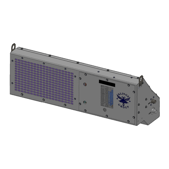
KLINGE CORPORATION Address: 4075 East Market Street York, PA 17402-5100 USA Telephone: 717.840.4500 Telefax: 717.840.4501 Corporate website - www.klingecorp.com SECTION SEVEN - SERVICE PARTS 7-1A Unit refrigeration outside view 7-1B Unit refrigeration with optional heater kit Unit refrigeration with covers removed... - Page 55 UNCONTROLLED WHEN PRINTED K35-TCR109-41/42 Rev. K, July 2023...
- Page 56 SECTION 7.1A UNIT REFRIGERATION OUTSIDE VIEW ITEM PART NO. DESCRIPTION QTY. 460-12850-41 UNIT GLYCOL (TCR-109-41) K21- 16379-05 CLAMP CONSTANT TORQU SS 1-1/16 360-12896-41 PANEL FRONT ASSY (TCR 109-41) K35-05896-00 LABEL GLYCOL IN K35-05897-00 LABEL GLYCOL OUT 060-12592-05 TUBE PVC CLEAR W/WIRE 1.5"Dx9"...
- Page 57 UNCONTROLLED WHEN PRINTED K35-TCR109-41/42 Rev. K, July 2023...
- Page 58 SECTION 7.1B UNIT REFRIGERATION WITH OPTIONAL HEATER KIT ITEM PART NO. DESCRIPTION QTY. HEATER REAR MTG 6 KW 460-13400-08 (INCLUDES ITEMS 2A & 3-16) HEATER REAR MTG 12 KW 460-13400-14 (INCLUDES ITEMS 2B & 3-16) K25-26356-06 HEATER IMMERSION 6KW 3PH 2” MPT K25-26356-12 HEATER IMMERSION 12KW 3PH 2”...
- Page 59 UNCONTROLLED WHEN PRINTED K35-TCR109-41/42 Rev. K, July 2023...
- Page 60 SECTION 7.2 UNIT REFRIGERATION WITH COVERS REMOVED ITEM PART NO. DESCRIPTION QTY. K15-00042-04 KIT VALVE DTC DISCH TEMP CONTL 060-13189-00 SPACER CHILLER MTG 360-12934-41 PUMP MTG ASSEMBLY (TCR 109-41) 360-12897-41 BLOWER ASSY (TCR 109-41) 360-12944-41 ASSY JUNCTION BOX (TCR 109-41) 360-13154-00 ASSEMBLY PLATE GLYCOL OUTLET 360 -13188-04...
- Page 61 UNCONTROLLED WHEN PRINTED K35-TCR109-41/42 Rev. K, July 2023...
- Page 62 SECTION 7.3 UNIT PUMP ASSEMBLY ITEM PART NO. DESCRIPTION QTY. 360-12934-41 MARINIZED MOTOR - PUMP - MOUNTING BRACKET , INSULATION AS COMPLETE "DROP IN" REPLACEMENT PART 360-13213-00 MARINIZED ELECTRICAL MOTOR (ONLY) 360-13212-00 MARINIZIED PUMP (ONLY) 060-12543-00 INSULATION KIT 060-12895-01 PUMP BRACKET 060-18297-01 CONNECTION GLYCOL 1"...
- Page 63 UNCONTROLLED WHEN PRINTED K35-TCR109-41/42 Rev. K, July 2023...
- Page 64 SECTION 7.4 PANEL BLOWER ASSEMBLY ITEM PART NO. DESCRIPTION QTY. 360-12897-41 PANEL BLOWER ASSY TCR-109-41 K26-25059-40 HOUSING BLOWER AL .06 THICK 750- K26-25060-00 RING INLET CONE AL 9.19D WHEEL K26-25061-00 WHEEL BLOWER DOUBLE INLET AL 9.1 K25-26570-20 GLAND EX CABLE ATEX M20 (0.43 – 0.56) K35-05606-00 LABEL ARROW 1"X 2"...
- Page 65 UNCONTROLLED WHEN PRINTED K35-TCR109-41/42 Rev. K, July 2023...
- Page 66 REFRIGERATION UNIT PARTS & PIPING SECTION 7.5 SCHEMATIC ITEM PART NO. DESCRIPTION QTY. K22-07026-00 VALVE SUCTION PRESS REGULATOR K26-17451-03 HEAT EXCHANGER 7/8 C X 3/8 C K22-06959-00 VALVE TANK 1/8 MPT TIRE STEM K26-25014-02 CHILLER 3 TON BOLTS ON BACK K25-26949-01 VALVE TX 7/8C X 1/2C 1/4 EQUAL K23-13408-00...
- Page 67 UNCONTROLLED WHEN PRINTED K35-TCR109-41/42 Rev. K, July 2023...
- Page 68 SMALL ELECTRICAL CONTROL BOX SECTION 7.6A DUAL PROBES ITEM PART NO. DESCRIPTION QTY. 460-17640-01 ELECT BOX ASSEMBLY (TCR 109 SMALL STYLE) 360-17641-41 DOOR ELECTRICAL BOX TCR-109 SMALL K29-17879-01 HINGE SLIP SS 9/32 HOLES SOCK RIGHT HAND K29-17880-01 HINGE SLIP SS 9/32 HOLES SOCK LEFT HAND 060-09113-00 INSULATOR HINGE 360-17648-00...
- Page 69 UNCONTROLLED WHEN PRINTED K35-TCR109-41/42 Rev. K, July 2023...
- Page 70 SMALL ELECTRICAL CONTROL BOX CABLE SECTION 7.6B HOOK-UP HEATER, FLOAT SWITCH & DUAL PROBES ITEM PART NO. DESCRIPTION QTY. 360-17648-01 CABLE ASSEMBLY MAIN POWER TCR-109 18M K25- 20474-00 PLUG POWER 32A 380/440V 3P+G WATER TIGHT 360-13807-00 KIT PROBE 6” UNIVERSAL 360-17648-03 CABLE POWER TO TCR-109 BOX TO UNIT 360-17648-02...
- Page 71 SECTION 7.7 EXPANSION TANK UNCONTROLLED WHEN PRINTED K35-TCR109-41/42 Rev. K, July 2023...
- Page 72 SECTION 7.7A GLYCOL EXPANSION TANK PLASTIC ITEM PART NO. DESCRIPTION QTY. TANK EXPANSION 4 GALLON PLASTIC 360-17659-00 (INCLUDES ITEMS 2 THRU 8) K26-25222-00 TANK GLYCOL POLYETHYLENE 4 GALLON K23-13395-00 ELBOW 90 BLACK POLYPROPYLENE K21-16379-03 CLAMP CONSTANT TORQUE 13/16 .812 - 1.5 RANGE K28-10897-02 HOSE HEAVY DUTY SPIRAL REINFORCED 1.00 ID K21-14072-00...
- Page 73 SECTION 7.7B GLYCOL EXPANSION TANK ALUMINUM ITEM PART NO. DESCRIPTION QTY. TANK EXPANSION 2.5 GALLON ALUMINUM 360-12829-01 (INCLUDES ITEMS 2 THRU 9) 060-13197-00 CONNECTION GLYCOL 1” NPT X 6” K23-13258-06 PLUG PIPE 1” STAINLESS STEEL K26-24792-01 CAP FUEL 2” NPS W/8” CHAIN 060-13283-01 TUBE PVC SPIRAL REINF K26-24768-00...
-
Page 74: Addendum - Dual Systems
TCR-109 unit. A-2 Dual System Configuration One main incoming power cable is necessary to provide power to the system. Klinge provides a power cable to carry power from one electrical control box to the other. -
Page 75: Dual System Alarm Codes
A.4 Dual System Alarm Codes All standard TCR-109 alarm codes are relevant. Two additional alarm codes may appear based on the requirements of communication between the two units. ALARM CODE ALARM NAME ALARM CONDITION ALARM CLEAR SUGGESTION FOR REPAIR If the systems have The alarm is cleared Set point set points 1°C or... -
Page 76: Dual System Electrical Schematics
A.5 Dual System Electrical Schematics UNCONTROLLED WHEN PRINTED K35-TCR109-41/42 Rev. K, July 2023... - Page 77 UNCONTROLLED WHEN PRINTED K35-TCR109-41/42 Rev. K, July 2023...
-
Page 78: Dual System Installation Kit Drawing
A.6 Dual System Installation Kit Drawing UNCONTROLLED WHEN PRINTED K35-TCR109-41/42 Rev. K, July 2023... -
Page 79: Dual System Control Box #1
A.7 Dual System Control Box #1 UNCONTROLLED WHEN PRINTED K35-TCR109-41/42 Rev. K, July 2023... -
Page 80: Dual System Control Box #2
A.8 Dual System Control Box #2 UNCONTROLLED WHEN PRINTED K35-TCR109-41/42 Rev. K, July 2023...
Need help?
Do you have a question about the TCR-109-41 and is the answer not in the manual?
Questions and answers