Table of Contents
Advertisement
Quick Links
Advertisement
Table of Contents

Related Manuals for JMC 2HSS858H

Summary of Contents for JMC 2HSS858H
- Page 1 2HSS858H Digital Stepper Servo Drive Manual Email:info@jmc-motion.com Address: Floor2, Building A, Hongwei Industrial Zone No.6, Liuxian 3rd Road, Shenzhen. China Shenzhen Just Motion Control Electro-mechanics Co., Ltd TEL:+86-0755-26509689 26502268 FAX:+86-0755-26509289 Http://www.jmc-motion.com...
- Page 2 Thanks for selecting JMC stepper motor driver. We hope that the superior performance, outstanding quality, excellent cost performance of our product can help you accomplish your motion control project. The content in this manual has been carefully prepared and is believed to be accurate, but no responsibility is assumed for inaccuracies.
-
Page 3: Table Of Contents
10.1 Button Panel Operation................. 21 10.2 Mode Configure Operation Example............22 10.3 Parameter Configure Operation Example............. 22 11. Typical Connections to 2HSS858H..............23 12. Processing Methods to Common Problems and Faults........24 12.1 Power on but no digital tube display.............24 12.2 Power on or after the motor running a small angle and fault data display..24... -
Page 4: Brief Introduction
1. Brief Introduction 1.1 Overview The 2HSS858H stepper servo drive system integrates the servo control technology into the digital stepper drive perfectly. This stepper servo driver uses the latest 32-bit DSP and combines the advanced servo algorithm to control. Compared to the traditional step drive, this step... -
Page 5: Applications
User-defined micro steps Compatible with 1000 and 2500 lines encoder No adjustment in general application Lack of phase, over current, over voltage and over position protection Six digital tube display, easy to set parameters and monitor the motor running state 1.3 Applications It is suitable for the automation equipment and instrumentation... - Page 6 Over voltage value 200VDC Protections The range of over position error can be set by the front panel or HISU Overall Dimensions(mm) 140×70×56 Weight Approximate 1500g Environment Avoid dust, oil fog and corrosive gasses Operating 0~70℃ Temperature Environment Storage -20℃~+65℃...
-
Page 7: Mechanical Specifications
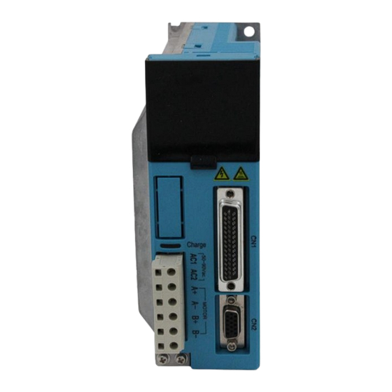
2.2 Mechanical Specifications Fig. 1 Mechanical installation size (unit: mm) Notice: Please take the terminal size and ventilation cooling while design the installation size. 2.3 Elimination of Heat Drive’s reliable working temperature should be <60 ℃ , and motor working temperature should be <90℃;... -
Page 8: Fault Data Display
3. Fault Data Display Data display Fault cause Over current in the motor Current sensor alarm Parameters upload alarm Over voltage in power supply Over position error alarm Missing phase alarm Drive off -line 4. Ports and Connections Introduction 4.1 Ports Definition 4.1.1 Power Interface Ports1 Port Symbol... -
Page 9: Control Signal Interface Ports (44 Pins Db)
4.1.2 Control Signal Interface Ports (44 Pins DB) Port Symbol Definition Remark Input port + Preserved function Input port - Preserved function PUL+ Pulse signal input + Compatible with 5V and 24V PUL- Pulse signal input - DIR+ Direction signal input + Compatible with 5V and 24V DIR-... -
Page 10: Rs232 Communication Interface Ports
Not Connection Attention: In case of causing any damage, please confirm the connection cables between 2HSS858H and HISU before using it. 4.1.4 Status Indicator 1. Control panel (including 5 buttons and 6 LED digital tube displays) panel includes six 7-segment digits and five keys for users operation as the picture show above. - Page 11 ‘ ’Button: Left shift Digits ‘ENT’Button: Enter or Confirm ‘▲’Button: Decrease or Next ‘M’Button: Exit Mode ‘▼’Button: Increase or Previous switching Function Setting LED Display Definition Remark d00SPF Reference Speed d01SPF Speed Feedback d02PLE Position Error d03PLR Position Reference d04PLF Position Feedback xx_Err Drive Failure...
-
Page 12: Connections To Control Signal
5. Connections to Control Signal The connections to the input and output control signals are as follows: Fig. 2 Connections to differential signals Fig. 3 Connections to common anode... -
Page 13: Sequence Chart Of Control Signal
Fig. 4 Connections to common cathode Attention: The control signal can be compatible with 5V and 24V. 6. Sequence Chart of Control Signal In order to avoid some fault operations and deviations, PUL, DIR and ENA should abide by some rules, shown as following diagram: Fig. -
Page 14: Connections To Encoder
The connection wires of the encoder are designed with the extension wires of 15 pins and the motor encoder wires, and these special wires are provided by our company, users no need to connect them. The definitions of the 2HSS858H encoder interface ports are as follows: DB Port Signal... -
Page 15: Connections To Serial Interface
2HSS858H and HISU before using it. 9. Drive’ Parameters Configure There two methods to configure parameters of 2HSS858H, one is set the parameters through the front panel, the other way is to connect it with the HISU.A set of the best default configure parameters has already set in... - Page 16 Speed loop Kp 0—3000 Speed loop Ki 0—1000 1000 Open-loop current 0—60 Close-loop current 0—40 P10 Alarm level 0—1 P11 Direction level 0—1 P12 Reservation Reservation Reservation Reservation Reservation P13 Enable level 0—1 P14 Arrival level 0—1 P15 Encoder line number 0—1 P16 Position error limit 0—3000...
- Page 17 P26 Damping coefficient 0—500 after stopping P27 Damping coefficient 0—500 at low speed P28 Reservation Reservation Reservation Reservation Reservation P29 Reservation Reservation Reservation Reservation Reservation P30 Close motor to detect 0—1 the lack of Phase P31 automatic detection 0—9000 4000 position P32 Self testing time 0—1000...
- Page 18 There are total 39 parameter configurations, use the HISU to download the configured parameters to the drive, the detail descriptions to every parameter configuration are as follows: Item Description Current loop Kp is adjusted to make current rise fast or not. Proportional Gain determines the response of the drive to setting command.
- Page 19 current (The actual current = open loop current + close loop current) Alarm This parameter is set to control the Alarm optocoupler Control output transistor. 1 means the transistor is cut off when the system is in normal working, but when it comes to fault of the drive, the transistor becomes conductive.
- Page 20 Speed speed of the motor while acceleration or deceleration, the smoothness larger the value, the smoother the speed in acceleration or deceleration. User-defined User can set the micro steps according the specific situation, the actual micro steps = the set value ×...
-
Page 21: Parameter Adjustment Method
from big to small circularly via‘▼’ , for example :”9, 8… 1, 9”; Adjust the opposite value via ‘▲’; Save the set parameter via ‘ENT’ when it is set correctly according to your adjustment; repeal the parameter to the original value via ‘M’, then return. -
Page 22: Mode Configure Operation Example
Fig. 7 Button operation flow diagram 10.2 Mode Configure Operation Example Fig. 8 Display operation flow diagram 10.3 Parameter Configure Operation Example... -
Page 23: Typical Connections To 2Hss858H
Pulses/revolution according to the necessity of the control system. 11. Typical Connections to 2HSS858H The typical connections to 2HSS858H are shown in figure 10. The power source grade AC50V ~ AC90V selection is based on the matching motor. -
Page 24: Processing Methods To Common Problems And Faults
Fig. 10 Typical connections to 2HSS858H Attention :R (3~5K) must be connected to control signal terminal. 12. Processing Methods to Common Problems and Faults 12.1 Power on but no digital tube display No power input, please check the power supply circuit. The voltage is too low. -
Page 25: After Input Pulse Signal But The Motor Not Running
The stepper servo drive is over voltage or under voltage. Please lower or increase the input voltage. Please check the motor phase wires if they are connected correctly,if not, please refer to the 4.1.1 and 4.1.2 Power Ports. ...
Need help?
Do you have a question about the 2HSS858H and is the answer not in the manual?
Questions and answers