Table of Contents
Advertisement
Quick Links
Advertisement
Table of Contents

Summary of Contents for Kallipr Captis Multi
- Page 1 Sewer Level Monitoring Installation Guide Version 3.0 Date: 18 July 2024...
-
Page 2: Table Of Contents
Work Instructions Step 1 – Install the Antenna 5 3.3.1 Step 2 – Install the Device and Sensor 3.3.2 Step 3 – Testing 3.3.3 Associated Documents Document Name Kallipr - Captis Multi Installation Guide Kallipr - Captis Pulse Lite Installation Guide... -
Page 3: Background
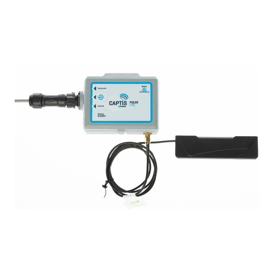
1. Background The Captis Pulse Lite is a fit for purpose IoT device which can be used to effectively and pro-actively monitor sewer level rises and trigger alarm based workflows as a result. Captis has been used for this purpose with large water authorities around the country for over 3 years. -
Page 4: Tools & Equipment
(LTE antenna, power cable, Amphenol connector, GPS antenna) and the device may be vulnerable. It is recommended that installers apply appropriate protection to this seal to ensure it is protected. If assistance is needed or you would like Kallipr to provide vermin-protection cables to help mitigate this risk, please contact Kallipr Support. -
Page 5: Work Instructions
3.3 Work Instructions These work instructions function as a basic guide to instruct the installer of the best practice workflow. It is understood that the installer may deviate from these guidelines based on the environmental factors at the time. The integrity of the device and float switch shall be prioritised when deviating from the following guide. - Page 6 3) Insert an eyebolt into the hole and screw it in the rest of the way using a screwdriver. Best practise is to rotate the eyebolt until tight but also with the eye piece in the horizontal position to allow for ease of attachment of the thimble and device.
-
Page 7: Step 2 - Install The Device And Sensor
Figure 5: Reference for Antenna channel 6) Cover the antenna and remaining cavity with road base. Carefully compact the road base and smoothen, taking care not to damage or apply force to the antenna. The surface should be returned to the original condition. a) Remove any debris. - Page 8 Note: Conduct a test to determine whether the float has the potential to become caught on benches, overflow windows and/or drop junctions 2) After confirming the length of float switch, wrap the chosen cable around a thimble, and cable tie tightly to create an anchor point. Figure 7: Reference for strain relief thimble 3) Cable tie the float switch to the eyebolt using the thimble and loop any excess lead.
-
Page 9: Step 3 - Testing
5) Use amalgamation tape to seal the connection point between the antenna and the device and the float switch and the device. 6) Reseal the antenna hole with silicon, mastic or clay and ensure the cable and antenna are reburied. 7) Use amalgamation tape to seal the connection point between the float and the device. - Page 10 With the device installed, the antenna and float switch terminated, and the MH cover replaced ensure that the device is connecting appropriately to the network. The functional test outlined above should ensure that data is available in your platform. If there are no signs of connectivity, please contact your support team.

Need help?
Do you have a question about the Captis Multi and is the answer not in the manual?
Questions and answers