
Related Manuals for Ideal Clima NEMO 250

Summary of Contents for Ideal Clima NEMO 250
- Page 1 Radiantore Nemo DC Inverter – Manuale per l’utente e per l’installatore RADIANTORE NEMO – DC INVERTER WIFI READY MANUALE PER L’UTENTE E PER L’INSTALLATORE...
-
Page 2: Table Of Contents
SMONTAGGIO DEL PANNELLO FRONTALE ....................28 FISSAGGIO A SOFFITTO E COLLEGAMENTO IDRAULICO ................. 31 COLLEGAMENTO ELETTRICO ........................33 8.10 AVVIAMENTO E COLLAUDO ........................35 CONDIZIONI DI GARANZIA ........................36 10 NOTE................................ 36 © Ideal Clima – Pagina 2 / 76... -
Page 3: Premessa
Leggere attentamente e rispettare scrupolosamente i seguenti suggerimenti: Il primo avviamento deve essere effettuato da personale qualificato e autorizzato dal produttore; © Ideal Clima – Pagina 3 di 76... -
Page 4: Interventi E Manutenzione
(anche se deboli) danneggiano la vernice e quindi favoriscono la formazione di ruggine. Non usare getti d’acqua o vapore su sensori, connettori e su qualsiasi altra parte elettrica. © Ideal Clima – Pagina 4 / 76... -
Page 5: Uso Previsto
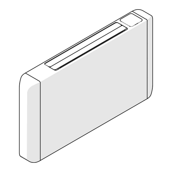
Rapido, efficace e a bassissima inerzia termica, scalda, raffredda e deumidifica gli ambienti nel massimo silenzio. Trova impiego negli impianti ad elevata temperatura per solo riscaldamento, quando la bassa inerzia termica e la silenziosità siano elementi importanti per la scelta del terminale d’impianto. STRUTTURA © Ideal Clima – Pagina 5 di 76... -
Page 6: Funzionamento
Temperatura ambiente compresa tra i 5 e i 40 °C – umidità tra 0 e 90% non condensante. • Temperatura dell’acqua compresa tra i 9° e i 90 °C in inverno e tra i 5° e i 20° C in estate. © Ideal Clima – Pagina 6 / 76... -
Page 7: Circuiti Elettrici
Le apparecchiature elettriche sono realizzate e cablate in accordo alle normative EN bassa tensione e compatibilità elettromagnetica. CABLAGGIO INTERNO Il collegamento a terra è obbligatorio. L'installatore deve provvedere al collegamento del cavo di terra. © Ideal Clima – Pagina 7 di 76... -
Page 8: Comandi E Funzionamento
• Cronotermostati programmatori o domotica in grado di fornire un segnale 0-10V • Sistema di controllo “Integra Benessere” di Ideal Clima, con interposto “Integra Control Zone” • Controllo tramite App con l’abbinamento all’accessorio WIFI+ (cod. TQCT07 – optional) © Ideal Clima – Pagina 8 / 76... -
Page 9: Controllo A Bordo
” lampeggiante) • Velocità auto (Led “ ” (Led acceso fisso). L’apparecchio modula la velocità in continuo in base alla temperatura ambiente e alla temperatura desiderata, con minimi consumi e massimo comfort. © Ideal Clima – Pagina 9 di 76... -
Page 10: Modifica Della Temperatura Target
Per ottenere la massima deumidificazione, in questa modalità la velocità di ventilazione è sempre la minima e non può essere cambiata. • I led “ ” e “ ” lampeggiano rispettivamente quando l’acqua di alimentazione è troppo calda nelle modalità © Ideal Clima – Pagina 10 / 76... -
Page 11: Controllo Esterno
(ad esempio se si desidera in inverno e della ventilazione con aria calda in utilizzare il dispositivo al di fuori delle fasce orarie estate impostate sul controllo esterno) © Ideal Clima – Pagina 11 di 76... -
Page 12: Collegamento Wifi
Tramite l’assistente virtuale Alexa è possibile gestire alcune delle funzioni del dispositivo con i Comandi vocali (vedi tabella a seguire per i comandi disponibili): Hey Alexa, accendi “nome dispositivo” Hey Alexa, imposta “nome dispositivo” su 25 gradi © Ideal Clima – Pagina 12 / 76... -
Page 13: Regolazione Dei Flap Di Uscita Aria
FLAP. Se si vuole una velocità maggiore si consiglia di scegliere una posizione tale dei FLAP che direzioni l’aria dove comodo per il cliente Procedere alla regolazione della posizione come sotto indicato: © Ideal Clima – Pagina 13 di 76... - Page 14 Scegliere la posizione preferita per la direzione dell’aria e rilasciare Quando Nemo non viene utilizzato è possibile richiudere i Flap seguendo le seguenti indicazioni: Ruotare i Flap premendo la parte superiore del Flap anteriore fino alla completa chiusura. © Ideal Clima – Pagina 14 / 76...
-
Page 15: Impostazioni Avanzate E Parametri
Comando 1=Invia il comando all’attuatore della valvola. attuatore 0 = non invia il comando Riservato Non usare Selezione unità misura temperatura. Scala delle 0 = gradi Celsius temperature 1 = gradi Fahrenheit © Ideal Clima – Pagina 15 di 76... -
Page 16: Dimensioni
Regola l’intensità luminosa dei led del display a bordo 5-20 DIMENSIONI CODICE DESCRIZIONE [mm] [mm] TNM02D NEMO 250 TNM04D NEMO 400 TNM06D NEMO 600 1’160 TNM08D NEMO 800 1’350 1.038 TNM10D NEMO 1000 1’350 1.038 © Ideal Clima – Pagina 16 / 76... -
Page 17: Post Vendita
Modificare il parametro 20 da 0 a raffrescamento sonda temperatura ventilatore si avvia. Dopo ambiente è investita da aria ventilatore, l’attivazione il primo arresto non riparte fredda intermittente, sposta l’aria fredda che lambisce la sonda. © Ideal Clima – Pagina 17 di 76... -
Page 18: Manutenzione Ordinaria
Per garantire nel tempo un funzionamento ottimale e silenzioso dell’unità è consigliato di pulire i filtri almeno ogni sei mesi e di sostituirli ogni due anni. Per rimuovere i filtri seguire le illustrazioni sotto. © Ideal Clima – Pagina 18 / 76... - Page 19 Ruotare leggermente i filtri Pulire i filtri con acqua (o sostituirli se necessario) Reinserire i filtri nella loro sede avendo cura che Ruotare il filtro gli incastri posteriori siano in posizione © Ideal Clima – Pagina 19 di 76...
-
Page 20: Messa Fuori Servizio Dell'unità
7 MESSA FUORI SERVIZIO DELL’UNITÀ Quando l’unità giunge al termine della durata prevista, i componenti non riutilizzabili vanno suddivisi secondo il loro genere merceologico e conferiti a impianti specializzati per riciclo o smaltimento. © Ideal Clima – Pagina 20 / 76... -
Page 21: Installazione
• In prossimità di fonti di calore. • In aree umide o con rischio di contatto con l’acqua. • In ambienti con presenza di fumi pure residui di combustione di gasolio e altri idrocarburi. © Ideal Clima – Pagina 21 di 76... -
Page 22: Installazione A Parete E Collegamento Idraulico
[mm] TNM02D NEMO 250 TNM04D NEMO 400 TNM06D NEMO 600 1160 TNM08D NEMO 800 1350 1038 1160 TNM10D NEMO 1000 1350 1038 1160 N.B. Gli attacchi idraulici si trovano sul lato sinistro. © Ideal Clima – Pagina 22 / 76... - Page 23 6 tasselli a espansione Con una livella verificare l’allineamento orizzontale delle due mensole. Togliere le 2 viti che bloccano in posizione i Posizionare a terra l’unità fianchi laterali © Ideal Clima – Pagina 23 di 76...
- Page 24 Si consiglia di installare, se possibile, gli accessori idraulici come Valvola a 2 vie o a 3 vie a macchina ancora a terra ed utilizzare dei tubi flessibili per il collegamento all’impianto. (vedi capitolo 8.4) © Ideal Clima – Pagina 24 / 76...
-
Page 25: Kit Per Collegamento Idraulico
KIT DI COLLEGAMENTO A TRE VIE: N.B. Fare attenzione alla posizione del simbolo impresso sulla valvola a tre vie. KIT DI COLLEGAMENTO A DUE VIE CON DETENTORE: © Ideal Clima – Pagina 25 di 76... - Page 26 Sostituire sulla valvola a 2 vie o 3 vie il tappo di plastica con la testina elettrotermica Infilare il cavo della testina nel passaggio ricavato nella parte inferiore/posteriore di Nemo e collegarlo ai morsetti elettrici dedicati (vedi capitolo collegamenti elettrici). © Ideal Clima – Pagina 26 / 76...
-
Page 27: Montaggio Dei Piedini
Eventualmente posizionarla come in figura 3 - Montaggio piedini di supporto a terra Posizionare i piedini nel verso indicato in figura e fissare gli stessi con le viti M4x8 o M4x12 © Ideal Clima – Pagina 27 di 76... -
Page 28: Aggancio A Parete E Viti Di Sicurezza
Se non fosse stato possibile eseguire l’installazione degli accessori idraulici con macchina a terra, e dovesse essere poco accessibile dal lato (ad esempio installazione in nicchia), è possibile smontare la parete frontale secondo le seguenti indicazioni. © Ideal Clima – Pagina 28 / 76... - Page 29 (il numero di viti Identificare sul retro lato sinistro la vite superiore varia secondo la taglia, 3 per Nemo 250, 4 per di fissaggio della parete frontale e rimuoverla Nemo 400 e 5 per Nemo 600) Ora è...
- Page 30 Radiantore Nemo DC Inverter – Manuale per l’utente e per l’installatore Rimontare i fianchi laterali, avvicinandoli alla Rimontare le 2 viti che bloccano in posizione i parete frontale e facendoli scorrere fianchi laterali leggermente verso il basso L’installazione è completata © Ideal Clima – Pagina 30 / 76...
-
Page 31: Fissaggio A Soffitto E Collegamento Idraulico
Per maggiore sicurezza, l’installazione a soffitto richiede l’ancoraggio del telaio con due ulteriori tasselli a espansione (non forniti) da inserirsi nei fori precedentemente praticati, come indicato in figura. Per maggiore sicurezza applicare le viti di bloccaggio inferiori. © Ideal Clima – Pagina 31 di 76... - Page 32 Per maggiore sicurezza applicare le viti di bloccaggio inferiori. SCARICO CONDENSA Collegare il tubo flessibile isolato in dotazione con l’apparecchio, come in figura: Mantenere l’apparecchio in leggera pendenza verso lo scarico condensa, per favorire il deflusso della condensa. © Ideal Clima – Pagina 32 / 76...
-
Page 33: Collegamento Elettrico
(filo blu) e per la fase (filo marrone). All’esterno della scatola elettrica sono portati anche i morsetti per il collegamento del comando esterno 0-10V(Filo nero=GND; filo rosso 0-10V) Per il Cablaggio non è necessario aprire il contenitore Scheda. Tutti i connettori per il funzionamento sono esterni © Ideal Clima – Pagina 33 di 76... - Page 34 Radiantore Nemo DC Inverter – Manuale per l’utente e per l’installatore © Ideal Clima – Pagina 34 / 76...
-
Page 35: Avviamento E Collaudo
Se si utilizza un comando esterno (si veda paragrafo 4.5) bisogna impostare il parametro 9 a 1 altrimenti il dispositivo ignorerà il comando esterno Verificare che tutti i collegamenti (idraulici, elettrici e aeraulici) siano installati correttamente e che siano osservate tutte le indicazioni riportate su etichette e manuale utente. © Ideal Clima – Pagina 35 di 76... -
Page 36: Condizioni Di Garanzia
Ideal Clima garantisce i propri prodotti per vizi o difetti di fabbricazione, con espressa esclusione di ogni vizio o fatto inerente all’installazione, alla conduzione ed alla manutenzione del prodotto. - 15.2 Soggetti destinatari - Ideal Clima fornisce prodotti unicamente ad imprese professionali. - Page 37 1 FOREWORD The user and maintenance manual should be used as follows: every operator and personnel assigned to the use and maintenance of the unit shall read this manual entirely and with the utmost attention and comply with what is stated; The employer must ensure that the operator has the necessary aptitude to operate the unit and has carefully read the manual;...
- Page 38 Place the unit in environments where there are no explosion, corrosion, or fire hazards and where vibration and electromagnetic fields are not present. Do not operate other than as directed and do not neglect operations necessary for safety. © Ideal Clima – Pagina 38 / 76...
- Page 39 Fast, effective, and with very low thermal inertia, it heats, cools, and dehumidifies rooms in complete silence. Find use in high temperature installations for heating only, when the low thermal inertia and noise are important elements for the choice of the system terminal. STRUCTURE © Ideal Clima – Pagina 39 di 76...
- Page 40 10 minutes, and the probes can measure the room air temperature. OPERATING LIMITS • Ambient temperature between 5 and 40°C-humidity between 0 and 90% non-condensing. • Water temperature between 9° and 90° C in winter and 5° and 20° C in summer. © Ideal Clima – Pagina 40 / 76...
- Page 41 Electrical equipment is manufactured and wired in accordance with EN low voltage and electromagnetic compatibility standards. INTERNAL WIRING The ground connection is required. The installer must make the connection of the ground wire. © Ideal Clima – Pagina 41 di 76...
- Page 42 • Programmable chronothermostats or home automation that can provide a 0-10V signal • Ideal Clima's "Integra Benessere" control system, with "Integra Control Zone" in between. • Control via App by pairing with WIFI+ accessory (cod. TQCT07 - optional) © Ideal Clima – Pagina 42 / 76...
- Page 43 " flashing) • Auto speed (Led " " (Led on steady). The device modulates the speed continuously according to the room temperature and the desired temperature, with minimum consumption and maximum comfort. © Ideal Clima – Pagina 43 di 76...
- Page 44 • The LEDs " " and " " flash respectively when the supply water is too hot in cooling and dehumidification modes or too cold in heating mode. © Ideal Clima – Pagina 44 / 76...
- Page 45 Before using the Wi-Fi connection for the first time you need to configure the WI-FI signal and settings via your smartphone or Tablet, this will enable communication between the connected devices. It is recommended that Bluetooth also be enabled for quick device recognition. © Ideal Clima – Pagina 45 di 76...
- Page 46 Through the Google Assistant, it is possible to manage much of the device's functions directly with Voice Commands (see table below for available commands): Ok Google, turn on "device name" All right, I turn on "device name" © Ideal Clima – Pagina 46 / 76...
- Page 47 Proceed to adjust the position as shown below: Place fingers inside the front flap at the extreme sides of the front flap, the back flap will move at Gently rotate upward the same time © Ideal Clima – Pagina 47 di 76...
- Page 48 N.B. Throughout the period of access to advanced functions, the two LEDs located at remain lit. MEANING OF PARAMETERS The following is the list of parameters and their meaning: © Ideal Clima – Pagina 48 / 76...
- Page 49 0 = the display always stays on when the fan coil is time powered 1 = the display turns off 30 seconds after the last touch Light Intensity Adjusts the light intensity of the LEDs on-board display 5-20 © Ideal Clima – Pagina 49 di 76...
- Page 50 35 minutes to perform a reset. respond setting Insert batteries again. If the remote control still does not work, contact service. Water overflows from Check that the condensate drain Clogged condensate drain condensate drain pan is clear. © Ideal Clima – Pagina 50 / 76...
- Page 51 Presence of condensation Incorrect thermal insulation Contact support drops on the front panel The airflow is weaker than Clean, or if appropriate, replace usual and the device Dirty filters the filters noisier © Ideal Clima – Pagina 51 di 76...
- Page 52 To remove filters follow the illustrations below. The filters have automatic anchor hooks that Identify the filter locking screws and disassemble must be pressed to release the filters from the them frame by pressing © Ideal Clima – Pagina 52 / 76...
- Page 53 Verify that the automatic hooks are well Insert the locking screws positioned CLEANING THE UNIT Clean the unit only with a damp, soft cloth. To avoid damaging the unit's paint, do not use abrasive sponges or harsh cleaners. © Ideal Clima – Pagina 53 di 76...
- Page 54 Do not install the unit outdoors and avoid exposure to weather such as rain, hail, moisture and frost. The following minimum distances from the device must be observed for proper operation: Do not place the device: • In direct exposure to sunlight. • Near heat sources. © Ideal Clima – Pagina 54 / 76...
- Page 55 TNM02D NEMO 250 TNM04D NEMO 400 TNM06D NEMO 600 1160 TNM08D NEMO 800 1350 1038 1160 TNM10D NEMO 1000 1350 1038 1160 N.B. The hydraulic connections are located on the left side. © Ideal Clima – Pagina 55 di 76...
- Page 56 Using a spirit level, check the horizontal alignment of the two brackets. Remove the 2 screws that lock the side panels in Place the unit on the ground place © Ideal Clima – Pagina 56 / 76...
- Page 57 It is recommended that, if possible, hydraulic accessories such as 2-way or 3-way valve be installed with the machine still on the ground and use hoses to connect to the system. (see chapter 8.4) © Ideal Clima – Pagina 57 di 76...
- Page 58 Hydraulic connection, can be made with 2-way or 3-way thermostatable valve as an alternative to manifold distribution with thermostatable outlets. THREE-WAY CONNECTION KIT: N.B. Pay attention to the position of the symbol imprinted on the three-way valve. TWO-WAY CONNECTION KIT WITH LOCKSHIELD: © Ideal Clima – Pagina 58 / 76...
- Page 59 Replace on the 2-way or 3-way valve the plastic cap with the electrothermal head Thread the actuator cable through the passageway cut in the bottom/back of Nemo and connect it to the dedicated electrical terminals (see electrical connections chapter). © Ideal Clima – Pagina 59 di 76...
- Page 60 Possibly place it as in the figure 3 - Mounting ground support feet Place the feet in the direction shown in the figure and secure them with M4x8 or M4x12 screws © Ideal Clima – Pagina 60 / 76...
- Page 61 If the installation of the plumbing accessories could not be carried out with the machine on the ground, and it should be poorly accessible from the side (e.g., installation in an alcove), the front wall can be disassembled according to the following directions. © Ideal Clima – Pagina 61 di 76...
- Page 62 Identify the front wall mounting screws on the bottom and remove them (number of screws Identify on the back left side the upper front wall varies by size, 3 for Nemo 250, 4 for Nemo 400, fixing screw and remove it and 5 for Nemo 600)
- Page 63 Refit the side panels, bringing them closer to the Reinstall the 2 screws that lock the side panels in front wall and sliding them down slightly place Installation is completed © Ideal Clima – Pagina 63 di 76...
- Page 64 Nemo has the standard connections on the left side. • It is possible to make the connection using the code "TGCL86 - Nemo 250/400/500 right side connection kit." The kit is the same for Nemo 250, Nemo 400, and Nemo 600 sizes.
- Page 65 Using a spirit level, check the horizontal alignment of the two brackets. Remove the 2 screws that lock the side panels in Place the unit on the ground place © Ideal Clima – Pagina 65 di 76...
- Page 66 Nemo and out the located under the condensate drain pan to the other side, then connect the pipe itself by back wall making a small siphon to the condensate drain © Ideal Clima – Pagina 66 / 76...
- Page 67 On the right side of Nemo, cut the copper pipe to the length that will be indicated. Insert plastic grommets to protect the holes Insert ½" fittings for 14-mm copper pipe © Ideal Clima – Pagina 67 di 76...
- Page 68 It is possible to vent the coil by acting on the air vent included in the kit. If the connection was made with multilayer pipe, first purge from the vent located on the coil, and then flush the unit with high water flow rates to remove any residual air in the circuit. © Ideal Clima – Pagina 68 / 76...
- Page 69 For added security, ceiling installation requires anchoring the frame with two additional expansion anchors (not provided) to be inserted into the previously drilled holes, as shown in the figure. For added security, apply the lower locking screws. © Ideal Clima – Pagina 69 di 76...
- Page 70 For added security, apply the lower locking screws. CONDENSATE DRAIN Connect the insulated hose supplied with the appliance as shown: Keep the appliance at a slight slope toward the condensate drain to promote condensate runoff. © Ideal Clima – Pagina 70 / 76...
- Page 71 (brown wire). Also carried on the outside of the electrical box are the terminals for connecting the external 0-10V control(Black wire=GND; red wire 0-10V) To wire, it is not necessary to open the PCB enclosure. All connectors for operation are external © Ideal Clima – Pagina 71 di 76...
- Page 72 Radiantore Nemo DC Inverter – Manuale per l’utente e per l’installatore © Ideal Clima – Pagina 72 / 76...
- Page 73 If you use an external command (see section 4.5) you must set parameter 9 to 1 otherwise the device will ignore the external command Verify that all connections (plumbing, electrical, and aeraulic) are properly installed and that all directions on labels and user manual are followed. © Ideal Clima – Pagina 73 di 76...
- Page 74 Norm 1999/44 / EC and D. Leg nr. 24 of 2 February 2002. The warranty is limited to the products provided by Ideal Clima and only to the customer. Ideal Clima reserves the right to apply their own...
- Page 75 © Ideal Clima – Pagina 75 di 76...
- Page 76 Tel. +39.030.35.45.319 – Fax +39 030.51.09.329 info@idealclima.eu – www.idealclima.eu Versione 6 – giugno 2024 In un processo di costante miglioramento, la società di riserva il diritto di apportare modifiche al prodotto in qualunque momento, anche senza preavviso. © Ideal Clima – Pagina 76 / 76...
Need help?
Do you have a question about the NEMO 250 and is the answer not in the manual?
Questions and answers