Table of Contents
Advertisement
Available languages
Available languages
Quick Links
Advertisement
Table of Contents

Related Manuals for Ideal Clima FALKO OC 510

Summary of Contents for Ideal Clima FALKO OC 510
- Page 1 FANCOIL FALKO A SOFFITTO OC STANDARD MANUALE PER L’UTENTE E PER L’INSTALLATORE...
-
Page 2: Table Of Contents
CONDIZIONI DI GARANZIA ........................24 10 NOTE..................ERRORE. IL SEGNALIBRO NON È DEFINITO. 11 FOREWORD ............................. 25 11.1 RESPONSIBILITY ............................. 25 11.2 OPERATING DIRECTIVES ..........................25 11.3 OPERATIONS AND MAINTENANCE ......................26 11.4 INTENDED USE .............................. 27 © Ideal Clima – Pagina 2 /... - Page 3 18.5 INSTALLATION OF PLUMBING KITS ......................37 18.6 INSTALLATION OF AIR PLENUMS FOR DUCTWORK ................... 38 18.7 ELECTRICAL CONNECTION ........................41 18.8 STARTING ..............................45 19 WARRANTY CONDITIONS ........................45 20 NOTE................................ 46 © Ideal Clima – Pagina 3 di...
-
Page 4: Premessa
Leggere attentamente e rispettare scrupolosamente i seguenti suggerimenti: Il primo avviamento deve essere effettuato esclusivamente da personale qualificato e autorizzato dal produttore; © Ideal Clima – Pagina 4 /... -
Page 5: Interventi E Manutenzione
- effettuata la pulizia dell’unità l’operatore dovrà verificare che non vi siano parti logorate o danneggiate o non solidamente fissate, in caso contrario chiedere l’intervento del tecnico di manutenzione; © Ideal Clima – Pagina 5 di... -
Page 6: Uso Previsto
20. Il motore ha tre ingressi in fase per la selezione della velocità. Il telaio è in lamiera zincata. Il filtro aria è estraibile, sulla ripresa. Attacchi acqua, 3/4” F posti sul lato sinistro, sono reversibili in cantiere. © Ideal Clima – Pagina 6 /... -
Page 7: Struttura
Per comandare agevolmente l’unità, è consigliato l’impiego del cronotermostato a tre velocità (optional – cod. TGCL74) o di termostati e cronotermostati a commercio per fan coil a tre velocità. © Ideal Clima – Pagina 7 di... -
Page 8: Limiti Operativi
In modulazione 0-10V con Modulo specifico (optional – cod. TGKL80) • Termostati e cronotermostati a commercio per fan coil. • In modulazione con Plenum Multieasy COMANDI A BORDO Non sono previsti comandi a bordo macchina. © Ideal Clima – Pagina 8 /... -
Page 9: Dati Tecnici
(1) Temp. Acqua in ingresso 7°, Δ T 5 °C, Temp. Ambiente 27 °C UR 47% (UNI EN 1397 :2015) (2) Temp. Acqua in ingresso 45°, Δ T 5 °C Temp. Ambiente 20 °C (UNI EN 1397:2015) (*) Pressione sonora (dBA) r=1,5m, Q=1 (UNI EN ISO 3741:2010) 5.1 DIMENSIONI © Ideal Clima – Pagina 9 di... -
Page 10: Post Vendita
Porre l’interruttore generale nella posizione “spento”. -Estrarre il filtro dell’aria Sfilare lateralmente i filtri dalle staffe di supporto: -Pulire o sostituire i filtri Lavare i filtri con acqua, ma per toglierne la parte residua non strizzare i filtri. © Ideal Clima – Pagina 10 /... -
Page 11: Messa Fuori Servizio Dell'unità
Quando l’unità giunge al termine della durata prevista e ha bisogno di essere rimossa e sostituita, la struttura e i vari componenti, se inutilizzabili, vanno demoliti e suddivisi a seconda del loro genere merceologico. © Ideal Clima – Pagina 11 di... -
Page 12: Installazione
Verificare che la struttura edile su cui fissare l’unità sia sufficientemente robusta da sopportarne il peso, che sia piana per aderire correttamente all’unità e che non presenti ostacoli al regolare flusso dell’aria sia in presa che in espulsione. © Ideal Clima – Pagina 12 /... -
Page 13: Fissaggio A Soffitto
La bocca di ripresa dell’aria si trova orientata di fabbrica verso il basso dell’unità. La ripresa può essere orientata verso l’alto, in cantiere, con alcuni semplici passaggi. Di seguito è dettagliata la sequenza dal retro l basso. © Ideal Clima – Pagina 13 di... - Page 14 Rimontare la parete appena rimossa sul lato posteriore dell’unità, con la piega della lamiera posta in basso e rivolta verso l’interno dell’unità Fissare la parete con le viti Montare le staffe portafiltro sulla parete inferiore © Ideal Clima – Pagina 14 /...
-
Page 15: Attacchi Idraulici
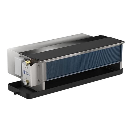
La mandata è contrassegnata da “IN”, il ritorno da “OUT”. Su entrambi gli attacchi è fissato uno sfiato per l’aria. Per stringere i raccordi usare sempre chiave e controchiave per evitare di rompere la batteria di scambio. © Ideal Clima – Pagina 15 di... -
Page 16: Installazione Dei Kit Idraulici
Fare attenzione al ricadere all’interno della bacinella di simbolo dei flussi impresso sul corpo della valvola raccolta condensa, in caso contrario isolare i tubi. Disponibile isolante adesivo (cod. VPNA02) © Ideal Clima – Pagina 16 /... -
Page 17: Installazione Dei Plenum Aria Per Canalizzazione
INSTALLAZIONE DEI PLENUM ARIA PER CANALIZZAZIONE L’unità può essere canalizzata sia in mandata che in ripresa. Gli accessori e i kit di canalizzazione Ideal Clima oggetto del presente manuale, prevedono condotti DN 160 per la distribuzione ai diversi ambienti. I plenum di mandata e di ritorno, così... - Page 18 Rimuovere il filtro e le barre portafiltro, pezzi Il plenum di ripresa è riconoscibile per la non sono utilizzati con il plenum di ripresa. La conformazione della bocca rettangolare “a filtrazione deve essere effettuata sulle tutt’altezza”. singole bocchette di ripresa. © Ideal Clima – Pagina 18 /...
- Page 19 Posizionare il plenum in battuta contro il lato Fissare il plenum con le viti autofilettanti a posteriore dell’unità corredo, nei fori ricavati lungo tutti i lati. Posizionare e fissare il condotto DN 160. Ripetere l’operazione per gli atri condotti. © Ideal Clima – Pagina 19 di...
-
Page 20: Collegamento Elettrico
16 bar. ISOLAMENTO TUBI Isolare i tubi scoperti che si trovano all’esterno della cassetta di predisposizione. È disponibile il nastro termoisolante (cod. VPNA02) COLLEGAMENTO ELETTRICO CON TERMOSTATO E CRONOTERMOSTATO A COMMERCIO PER FANCOIL © Ideal Clima – Pagina 20 /... - Page 21 Falko OC – Manuale per l’utente e per l’installatore CON CRONOTERMOSTATO A 3 VELOCITÀ “TGCL74” DI IDEAL CLIMA © Ideal Clima – Pagina 21 di...
- Page 22 Falko OC – Manuale per l’utente e per l’installatore CON INSTALLATO MODULO 0-10 V “TGKL80” DI IDEAL CLIMA © Ideal Clima – Pagina 22 /...
- Page 23 Falko OC – Manuale per l’utente e per l’installatore CON INSTALLATO PLENUM MULTIEASY In questo caso, per il collegamento dei termostati, riferirsi al manuale specifico del Plenum Multieasy © Ideal Clima – Pagina 23 di...
-
Page 24: Avviamento
Ideal Clima garantisce i propri prodotti per vizi o difetti di fabbricazione, con espressa esclusione di ogni vizio o fatto inerente all’installazione, alla conduzione ed alla manutenzione del prodotto. - 15.2 Soggetti destinatari - Ideal Clima fornisce prodotti unicamente ad imprese professionali. -
Page 25: Foreword
Carefully read and strictly observe the following prescriptions: Initial start-up should be carried out only by qualified personnel authorized by the manufacturer; © Ideal Clima – Pagina 25 di... -
Page 26: Operations And Maintenance
For cleaning the unit does not use diesel, petrol or solvents as the former leave an oily layer that promotes adhesion of dust, while solvents (although weak) damage the paint and thus favor the formation of rust. If a jet © Ideal Clima – Pagina 26 /... -
Page 27: Intended Use
The frame is made of galvanized metal sheet. The air filter is removable, on the intake. Water connections, 3/4" F located on the left side, are reversible on site. © Ideal Clima – Pagina 27 di... -
Page 28: Structure
To easily control the unit, it is recommended to use the three-speed chronothermostat (optional - code. TGCL74) or commercially available thermostats and chronothermostats for three-speed fan coils. © Ideal Clima – Pagina 28 /... -
Page 29: Operating Limits
In 0-10V modulation with specific Module (optional - code. TGKL80) • Commercially available thermostats and chronothermostats for fan coils. • In modulation with Plenum Multieasy 13.1 ON-BOARD CONTROLS No on-board controls are provided. © Ideal Clima – Pagina 29 di... -
Page 30: Technical Datai
(1) Temp. Inlet water 7°, Δ T 5 °C, Temp. Room 27 °C RH 47% (UNI EN 1397 :2015) (2) Temp. Inlet water 45°, Δ T 5 °C Temp. Environment 20 °C (UNI EN 1397:2015) (*) Sound pressure (dBA) r=1.5m, Q=1 (UNI EN ISO 3741:2010) 14.2 DIMENSIONS © Ideal Clima – Pagina 30 /... -
Page 31: After Sale
Place the main switch in the "off" position. -Extract the air filter. Pull the filters sideways out of the support brackets: -Cleanor replace filters Wash the filters with water, but to remove the residual part, do not squeeze the filters. © Ideal Clima – Pagina 31 di... -
Page 32: Decommissioning The Unit
When the unit reaches the end of its intended service life and needs to be removed and replaced, the structure and various components, if unusable, should be demolished and broken down according to their commodity type. © Ideal Clima – Pagina 32 /... -
Page 33: Installation
Ensure that the building structure to which the unit is to be fixed is strong enough to support its weight, that it is level to properly adhere to the unit, and that there are no obstructions to the smooth flow of air both in intake and exhaust. 17.3 CEILING MOUNTING © Ideal Clima – Pagina 33 di... - Page 34 The air intake port is factory oriented toward the bottom of the unit. The intake can be directed upward at the construction site with a few simple steps. The sequence from back l down is detailed below. © Ideal Clima – Pagina 34 /...
- Page 35 Secure the wall with screws Mount the filter holder brackets on the lower wall © Ideal Clima – Pagina 35 di...
-
Page 36: Hydraulic Connections
3 / 4" female. The supply is marked by "IN," the return by "OUT." An air vent is attached to both connections. Always wrench counter wrench to tighten fittings to avoid breaking the exchange battery. © Ideal Clima – Pagina 36 /... -
Page 37: Installation Of Plumbing Kits
The uninsulated parts of the valve must fall in the figure. Pay attention to the flow symbol back inside the condensate drain pan, stamped on the valve body otherwise insulate the pipes. Adhesive insulation available (cod. VPNA02) © Ideal Clima – Pagina 37 di... -
Page 38: Installation Of Air Plenums For Ductwork
17.6 INSTALLATION OF AIR PLENUMS FOR DUCTWORK The unit can be ducted in both supply and return. The Ideal Clima accessories and ducting kits covered in this manual provide DN 160 ducts for distribution to different rooms. Supply and return plenums, as well as ducting kits and other air network accessories, must be ordered separately. - Page 39 Remove the filter and filter bars, pieces are not used with the recovery plenum. Filtration The intake plenum is recognizable by the "full- should be carried out on the individual height" rectangular mouth shape. intake vents. © Ideal Clima – Pagina 39 di...
- Page 40 Secure the plenum with the supplied self- side of the unit tapping screws in the holes drilled along all sides. Position and secure the DN 160 duct. Repeat the operation for the other ducts. © Ideal Clima – Pagina 40 /...
-
Page 41: Electrical Connection
(16 bar). Test the unit at 1.5 times the expected operating pressure, in any case not exceeding 16 bar. PIPE INSULATION Insulate the uncovered pipes that are outside the preparation box. Thermal insulating tape (cod. VPNA02) 17.7 ELECTRICAL CONNECTION WITH THERMOSTAT AND TRADE CHRONOTHERMOSTAT FOR FANCOILS © Ideal Clima – Pagina 41 di... - Page 42 Falko OC – Installer and user manual WITH 3-SPEED CHRONO-THERMOSTAT "TGCL74" BY IDEAL CLIMA © Ideal Clima – Pagina 42 /...
- Page 43 Falko OC – Installer and user manual WITH INSTALLED 0-10 V MODULE "TGKL80" OF IDEAL CLIMA © Ideal Clima – Pagina 43 di...
- Page 44 Falko OC – Installer and user manual WITH MULTIEASY PLENUM INSTALLED In this case, refer to the specific manual of the Multieasy Plenum for thermostat connection © Ideal Clima – Pagina 44 /...
-
Page 45: Starting
-15.6 Right call: Ideal Clima reserves the right to ask for a contribution for the intervention of the technical assistance centre authorized, starting from the seventh month of the warranty period. This contribution will be quantified in advance and will have to be paid directly to the CAT. -
Page 46: Note
Falko OC – Installer and user manual 19 NOTE ……………………………………………………………………………………………………………………………………………. ……………………………………………………………………………………………………………………………………………. ……………………………………………………………………………………………………………………………………………. ……………………………………………………………………………………………………………………………………………. ……………………………………………………………………………………………………………………………………………. ……………………………………………………………………………………………………………………………………………. ……………………………………………………………………………………………………………………………………………. ……………………………………………………………………………………………………………………………………………. ……………………………………………………………………………………………………………………………………………. ……………………………………………………………………………………………………………………………………………. ……………………………………………………………………………………………………………………………………………. ……………………………………………………………………………………………………………………………………………. ……………………………………………………………………………………………………………………………………………. ……………………………………………………………………………………………………………………………………………. ……………………………………………………………………………………………………………………………………………. ……………………………………………………………………………………………………………………………………………. ……………………………………………………………………………………………………………………………………………. ……………………………………………………………………………………………………………………………………………. © Ideal Clima – Pagina 46 /... - Page 47 Falko OC – Installer and user manual © Ideal Clima – Pagina 47 di...
- Page 48 Ideal Clima srl Brescia Italy Tel. +39.030.35.45.319 – Fax +39 030.51.09.329 info@idealclima.eu – www.idealclima.eu Versione 11- giugno 2024 In un processo di costante miglioramento, la società di riserva il diritto di apportare modifiche al prodotto in qualunque momento, anche senza preavviso.
Need help?
Do you have a question about the FALKO OC 510 and is the answer not in the manual?
Questions and answers