Table of Contents
Advertisement
Quick Links
Advertisement
Table of Contents

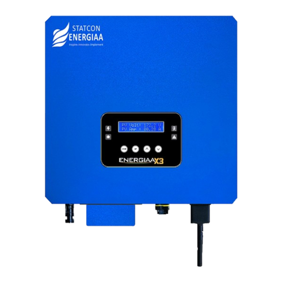
Summary of Contents for STATCON ENERGIAA Energiaa X3
-
Page 3: Table Of Contents
(including software, etc.) it. Reproduction or distribution of it in any form or by any means is not permitted. All rights reserved. STATCON ENERGIAA PVT. LTD. reserves the right of final interpretation. This document is subject to changes without prior notice. This is valid only for ENERGIAAX series String Inverter PCUs and not for our other custom-built ratings. -
Page 4: Notes On The Manual
1. NOTES ON THE MANUAL 1.1 SCOPE OF VALIDITY This manual is an integral part of the string inverter, and it describes the assembly, installation, commissioning, maintenance and failure analysis/ troubleshooting of string inverter. The manual does not include complete information about the photovoltaic (PV) system. -
Page 5: Product Safeguarding
1.4.3 PRODUCT SAFEGUARDING Inverter should be placed in accordance with the given instructions. (Follow Section 4.1) Routine checks should be carried out to monitor the system health. (Follow Section 7.1) The system works well in areas where temperature falls in range between -25ºC to +55ºC. ... -
Page 6: Operating Interface
Inverter Current & Temperature Grid Voltage & Frequency Time & Date PV Voltage & Current String Inverter Statcon Energiaa String Inv. Designed By Welcome Time-11:45:13 Solar Power Date-07/04/2024 02.285KW System ON PV Volt : 355.0V Grid Connected PV Amp : 10.09A... -
Page 7: Display Overview
3.3 DISPLAY OVERVIEW The display is located on the front panel of the inverter, which shows the following information: Check parameters after the inverter is switched ON. Press “Increment” button to see each parameter. Press “Enter” button to see fault messages. ... -
Page 8: Installation
4. INSTALLATION 4.1 LOCATION AND PLACEMENT To select a location for the inverter, the following criteria should be considered: Avoid installing the inverter in a potentially explosive atmosphere. Avoid installing the inverter in small closed spaces where air cannot circulate freely. ... -
Page 9: Inverter Installation
4.2 INVERTER INSTALLATION The inverter is designed according to the wall mounted type installation, please use the expansion bolt for sturdy wall mounting. Anchoring Mounting bracket Stainless steel screw Inverter Figure-4.3 Inverter installation 4.3 PROCEDURE FOR INSTALLATION On the wall, locate the appropriate area for the Bolt's position on the mounting bracket, and then mark the ... -
Page 10: Electrical Connections
5. ELECTRICAL CONNECTIONS 5.1 DC INPUT TERMINAL CONNECTION Warning ! Before connecting PV modules, please ensure the PV+ & PV- of solar panel is not connected to the system ground bar. Safety Hint: Before connecting, please ensure the polarity of the output voltage of PV array matches PV+ &... -
Page 11: Ac Input Terminal Connection
Insert the contact pin into the top part of the connector, screw up the cap nut to the top part of the connector (as shown in figure-5.5). Figure-5.5 connector Finally, insert the DC connector into the positive and negative inputs of the inverter (as shown in figure- ... - Page 12 1. Matching Socket 2. Sleeve 3. Sealing Core 4. Sealing Nut Figure-5.7 AC connector structure Use stripper to strip the protective sheath of the AC cable to the right length (as shown in figure 5.8). Figure-5.8 Strip AC cable Warning ! Please pay attention to distinguish the L, N and PE of the AC Cables.
-
Page 13: Connection Of The Ground Line
RS 485 GRID MOV BOX Figure-5.10 AC input connection 5.3 CONNECTION OF THE GROUND LINE Proper grounding is good for resisting surge voltage shock and improving EMI performance. Therefore, before connecting AC, DC cables and data-logger, you need to ground the cable first. For a single system, simply ground the PE (Potential Earth) cable. -
Page 14: Installation Of Data-Logger
5.5 INSTALLATION OF DATA-LOGGER When installing the data-logger, remove the sticker first. Insert the data-logger, as per correct connector orientation and tighten the screws to hold it tightly in position. When the inverter PV power is on, an orange LED will light up in the data-logger, indicating normal operation. -
Page 15: Inverter Shutdown
6.2 INVERTER SHUTDOWN Must follow below steps while shutting down the inverter : STEP 1 - Turn off the inverter, follow section 3.6. STEP 2 - Turn off the AC switch (if any), or simply disconnect the AC input connector. STEP 3 - Turn off the DC switch (if any), or simply disconnect the DC input connector. -
Page 16: Appendix-1 General Faults And Their Solutions
APPENDIX-1 GENERAL FAULTS AND THEIR SOLUTIONS FAULT NAME DESCRIPTION REMEDY/ACTION When grid supply voltage goes above the over- voltage Grid Over Volt Check the grid voltage set value When grid supply voltage goes below the under- Grid Under Volt Check the grid voltage voltage set value When grid supply frequency goes above the over- Contact your DISCOM to... -
Page 17: Appendix-2 Technical Specifications - Energiaa X3 - 3Kw Grid-Tied Solar Inverter
APPENDIX-2 TECHNICAL SPECIFICATIONS - ENERGIAA X3 3kW GRID-TIED SOLAR INVERTER Model No. Energiaa X3 INPUT SIDE 450V Max. DC Input Voltage Max. Recommended DC Power 3.3KW Start-Up DC Input Voltage 100V Nominal Voltage 380V MPPT Operating Range (Voc) 100-450V DC Max. - Page 18 Operating Temperature (-25 ~ +55) °C Night Time Power Consumption < 1W Cooling Natural Convection Ingress Protection IP-65 Relative Humidity 0~100% DC Connection AC Connection Connector Display 16 X 2 LCD Interface RS485/Wi-Fi Warranty 84 Months/ 7 Years ** PROTECTION Grid Monitoring Anti-Islanding Differential Current Monitoring...
-
Page 19: Appendix-3 Version History
APPENDIX-3 VERSION HISTORY VERSION HISTORY DETAILS VER. NO. RATING/MODEL NO. DATE COMMENTS Version 1.2 3KW String Inverter (Energiaa X3) 19-04-2024 No Comments Version 1.3 3KW String Inverter (Energiaa X3) 02-05-2024 Data Sheet Update Version 1.3... - Page 20 B-81, Sector-63, Noida, G.B. Nagar-201307 (U.P.) - INDIA Phone : +91-120-4088600, Toll Free : 1800 891 3319 Website : www.energiaa.in Customer Support : servicing@energiaa.in...


Need help?
Do you have a question about the Energiaa X3 and is the answer not in the manual?
Questions and answers