Subscribe to Our Youtube Channel
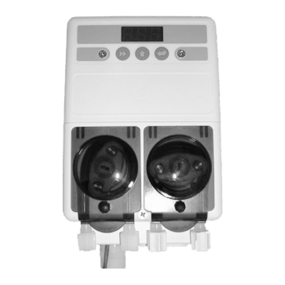
Summary of Contents for Hydro systems NOVA CONTROLS SPRITE DM-400 Series
- Page 1 Systems Company SPRITE WAREWASH DISPENSING SYSTEM Reference Manual DM-400 Series P/N 20-06270-00 Rev. D...
- Page 2 System Diagram Rinse Pump Discharge Tube Detergent Capsule Feeder Rinse Injection Fitting Solenoid Inlet Tube Solenoid Outlet Tube Detergent Bulkhead Fitting Rinse Pump Supply Tube Probe Wire Probe Electrical Conduit Rinse Product Container Page 2 P/N 20-06270-00 Rev. D...
-
Page 3: Description Of Features
1.0 DESCRIPTION OF FEATURES • Advanced Design • Save Money DESCRIPTION OF FEATURES The SPRITE uses miniaturized electronics to provide A special Rinse Saver Feature prevents rinse additive powerful features in a small package. A digital wastage during fills of the washer, digital electronics readout allows simple three button programming of ensure accurate detergent control and minimize all options. -
Page 4: Mechanical Installation
3.0 MECHANICAL INSTALLATION DESCRIPTION OF Figure 3.1 CAUTION: The Sprite dispensing system is FEATURES intended to be installed by experi- Unit Mounting—Wall enced installers in accordance with all applicable electrical and plumbing Mounting Bracket codes. All dish machine and dispenser power is to be disconnected during DESCRIPTION OF installation and/or any time the... - Page 5 Rinse Injection Fitting Figure 3.3 DESCRIPTION OF FEATURES The rinse injection fitting typically is to be installed Rinse Injection Fitting at least 6" below the dish machine rinse plumbing vacuum breaker to conform to plumbing codes. The Compression Fitting (tube from pump) injection fitting threads into 1/8"...
- Page 6 DESCRIPTION OF Rinse and Detergent FEATURES Supply and Discharge Tubes (Not Included) 3.5.a Route pump supply tubes from supply containers to the inlet sides (left) of each respective pump. Slip into compression DESCRIPTION OF CONTROLS fittings and tighten. 3.5.b Route pump discharge tubes to the outlet sides (right) of each respective pump.
-
Page 7: Electrical Installation
4.0 ELECTRICAL INSTALLATION Detergent Signal Wiring-Probe Mode The detergent signal input is an optically isolated DESCRIPTION OF All electrical connections except the probe are to be FEATURES signal input that draws no more than 20 ma. The done either in the dish machine control circuit panel detergent signal input is a universal AC voltage input or an external junction box. -
Page 8: User Mode Operation
5.0 USER MODE OPERATION DESCRIPTION OF NOTE: Please refer to illustrations on the 5.1.d De-Lime (Screen 14) FEATURES next page. Press the Next key to display 14. Press the Enter key In User Mode the SPRITE display indicates the to start the De-Lime Cycle time (10 minutes). During operating status of the dispenser. - Page 9 Visual Alarm Status Low Detergent Alarm Idle Home Screen Rinse Pump On Detergent Feed DESCRIPTION OF FEATURES Detergent Overfeed Stop Alarm 30 seconds, no activity Tens of Racks Rack Counter DESCRIPTION OF CONTROLS RAM Check MECHANICAL INSTALLTION = Reset Checksum Max Det Time (Probe Only) ELECTRICAL INSTALLATION...
- Page 10 Program Mode Screens Input Installer Password Configuration Settings Adjustments—Probe Adjustments—Probe-less Exit Program Mode User Mode 1 = Probe Detergent Control 2 = Probe-less Detergent Tank Reading Tank Reading Detergent Initial Charge Seconds 1 = Door Machine Type 2 = Conveyor Detergent Set Point Set Point Detergent Dose...
-
Page 11: Program Mode
Configuration Settings (screen 2) 6.0 PROGRAM MODE DESCRIPTION OF Program Mode consists of three circular main menu Input Installer Password FEATURES Configuration Settings loops. The Configuration Settings loop (2) is always available. There are two adjustment main menu loops, probe and probe-less. To simplify program- ming, only one adjustment main menu loop is 1 = Probe Detergent Control... - Page 12 DESCRIPTION OF 6.2.c Detergent Type (screen 23) 6.2.f Initial Charge, Probe-less Only FEATURES (screen 26) Press the Enter key to view/change this setting. Press the Scroll key to select between 1 (Liquid) and 2 NOTE: This setting only applies to probe-less (Capsule) detergent.
- Page 13 Adjustments—Probe NOTE: It is a good practice to run a few DESCRIPTION OF FEATURES racks through the dish machine and Adjustments—Probe retest concentration with a titration kit. If you find that the concentration is not at the desired level, adjust accordingly.
- Page 14 DESCRIPTION OF 6.3.f Rinse Delay Time (screen 36) 6.4.a Detergent Initial Charge (screen 41) FEATURES NOTE: This menu option is only available NOTE: Prepare for this reading by determin- when 1 (Door) is selected in screen 22 ing the detergent feed time (in (Machine Type) and rinse feed option seconds) required to charge the wash is set to 1 in screen 35.
-
Page 15: Troubleshooting
Detergent Pump Jammed: Press the Enter key to view/change this setting. Press DESCRIPTION OF FEATURES the Scroll key to change the blinking digit to the desired value. Press the Next key to move the blinking digit. Repeat for all digits. The range of this adjustment is from 0 to 59.5 RPM in 0.5 RPM steps. -
Page 16: Maintenance And Service
8.0 MAINTENANCE & SERVICE DESCRIPTION OF Service Disassembly Routine maintenance on the Sprite unit includes FEATURES The Sprite service parts are comprised of three major keeping the probe clean (probe mode operation assemblies, pump parts and tubes, and the solenoid only), keeping pump tubes fresh, and keeping the valve. -
Page 17: Spare Parts Listing
9.0 SPARE PARTS LISTING DESCRIPTION OF FEATURES DESCRIPTION OF CONTROLS MECHANICAL INSTALLTION ELECTRICAL INSTALLATION USER MODE OPERATION PROGRAM MODE ITEM DESCRIPTION PART NUMBER Printed Circuit Board, includes Cabinet Front and Terminal Barriers ......................13-06393-00 Printed Circuit Board (EU), includes Cabinet Front and Terminal Barriers ....................13-06393-01 TROUBLESHOOTING Cabinet Front Screw ...................................... - Page 18 10.0 SPECIFICATIONS DM-400 SERIES DESCRIPTION OF 10.0.1 Dimensions FEATURES Size: 6.0" (15.24 cm) wide X 10.75" (27.31 cm) high (with solenoid) 4.88" (12.38 cm) deep Weight: 5.98 lbs. (2.71 kilos) Temperature: 120° F Maximum 10.0.2 Power Requirements DESCRIPTION OF Total amperage draw during operation is: CONTROLS 90 to 130 VAC, 50/60 Hz.


Need help?
Do you have a question about the NOVA CONTROLS SPRITE DM-400 Series and is the answer not in the manual?
Questions and answers