Table of Contents
Advertisement
Quick Links
Advertisement
Table of Contents

Related Manuals for VWR avantor Ultrapure PS


Summary of Contents for VWR avantor Ultrapure PS
- Page 1 Instruction Manual Original Operating Instructions Ultrapure PS/PUV Water System ® Ultrapure ES/EUV Water System ® Ultrapure Water System EU Cat. No.: 171-1510, 171-1509, 171-1508, 171-1507 US Cat. No: 76777-136, 76777-138, 76777-140, 76777-142 1000130708 | Last updated: 05 | 2024...
- Page 2 Legal Address of Manufacturer VWR International, LLC 100 Matsonford Rd, Radnor PA 19087 www.vwr.com Europe VWR International bv, Researchpark Haasrode 2020 Geldenaaksebaan 464 B-3001 Leuven +3216385011 be.vwr.com UK Importer: VWR International Ltd Hunter Boulevard, Magna Park Lutterworth, Leicestershire, LE17 4XN uk.vwr.com...
-
Page 3: Table Of Contents
Rinsing the Ultrapure Cartridge ... . . 38 3.5.4 Final Purification Stage....14 6.8.1 Filling of the Bag (only VWR ® 3.5.5 Circulation of the Ultrapure Water ..14 Ultrapure PS/PUV Water System) . - Page 4 Water System)......52 17 Service, authorized by VWR..... . . 74 8.5.4 Replacing Ultrapure Cartridge .
-
Page 5: About This Document
About this Document About this Document Validity These instructions are part of the device. These instructions apply to the device in the following versions: Part Number Description VWR US VWR EU VWR US VWR EU Catalog Catalog number number 76777-140... -
Page 6: Safety Notes
The actions described are addressed to the “user” target group. If individual actions must be carried out by other target groups or by Service personnel, authorized by VWR: The qualification required will be indicated in the description of the action. -
Page 7: Significance Of These Instructions
Only operate the device when it is in proper working order. Comply with the maintenance intervals (for intervals and maintenance tasks, see Chapter “8.2 Maintenance Schedule,” page 49). Have any damage repaired immediately by Service, authorized by VWR. Operating Instructions... -
Page 8: Electrical Equipment
Working on the Electrical Equipment of the Device Any work on or modifications to the electrical equipment of the device may only be carried out by Service personnel, authorized by VWR. The device may only be opened by Service personnel, authorized by VWR. -
Page 9: Device Description
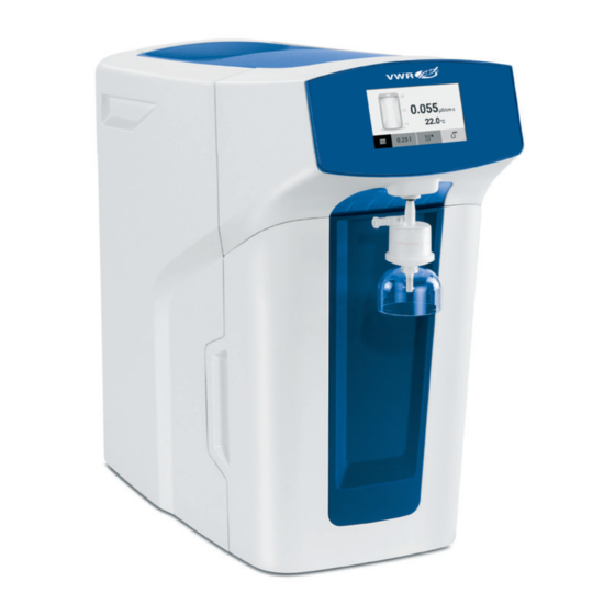
Device Description Device Description Device Overview Fig. 1: VWR Ultrapure PS Water System (example) ® Description Display with touch function Water outlet Final filter Front cover Side cover Operating Instructions... -
Page 10: Electrical Connections
Description Explanation “Inlet” con- For connecting the tank filling tubing or feed water nection tubing “Drain” con- For connecting the waste water tubing (only VWR ® nection Ultrapure PS/PUV Water System) “Bag Outlet” For connecting the tank outlet tubing (VWR ®... -
Page 11: Tubing
Device Description Tubing 3.4.1 Feed Water Tubing The feed water tubing is used to supply feed water to the device: — VWR Ultrapure PS/PUV Water System: Supply of tap water ® — VWR Ultrapure ES/EUV Water System: Supply of pretreated water ®... -
Page 12: Ultrapure Water Treatment
Device Description Ultrapure Water Treatment 3.5.1 System Setup Fig. 4: VWR Ultrapure PUV Water System setup ® Fig. 5: VWR Ultrapure EUV Water System setup ® Description Description Inlet (feed water) UV lamp (185/254 nm) Pump Ultrapure water cartridge Pretreatment cartridge... -
Page 13: Feed Water Intake
Device Description 3.5.2 Feed Water Intake The feed water intake differs according to the device type: Description Feed water intake Ultrapure PS/PUV Direct connection to tap water, automatic ® Water System filling of the bag Ultrapure ES/EUV Direct connection to pretreated water ®... -
Page 14: Final Purification Stage
The water fed in can be freed from organic residues using an optional UV lamp (185/254 nm). The pretreated water is then treated using the ultrapure water cartridge (VWR Ultrapure Polishing Cartridge). ® The quality of the ultrapure water is monitored via a conductivity measuring cell (LFP). -
Page 15: Operating Design
Operating Design Operating Design Menu All system settings and work steps for the maintenance of the device can be carried out in the menu. Fig. 6: Menu in VWR Ultrapure PS/PUV Water System (Example) ® Pos. Symbol Name Description Dispensing Opens the dispensing screen. -
Page 16: Dispensing Mode
Name Description Operating area Can display the following information: — Current ultrapure water conductivity — Current ultrapure water temperature — Fill level of the bag (only for VWR Ultrapure PS/PUV Water ® System) — Messages, warnings, errors Manual dispense Starts dispensing without preset dispense volumes. -
Page 17: Message Display
Operating Design Message Display The device displays three types of messages: — Error messages (error): — Dispense is not possible. — The user only has limited options for troubleshooting errors. — Warning messages (warning): — Dispense is possible. — The user can perform troubleshooting of warning messages. —... -
Page 18: Messages In Dispensing Mode
Indicates that there is a message about a value and opens the message list: — Red symbol: Error message — Yellow symbol: Warning message Bag fill level Only for VWR Ultrapure PS/PUV Water System: ® message — Indicates the fill level of the bag: —... -
Page 19: Message List
Displays and opens the message. Brief description Displays the error number or a short description of the mes- sage. Message category Displays the message category: — Error: Contact VWR. — Care: Replace the consumable. — Service: Contact VWR. Operating Instructions... -
Page 20: Numeric Keypad
Operating Design Numeric Keypad The numeric keypad is used to enter a dispensing volume or various system settings. Fig. 11: Numeric keypad (example: Time input) Pos. Symbol Name Description Name of the Displays the name of the current dialog box dialog box. -
Page 21: Navigating The Menus
Operating Design Navigating the Menus A display with touch function is provided for operating the device. If multiple menu items are available, you can use the touch screen to scroll up and down in order to select the desired entry. NOTICE Sharp or pointed instruments such as ballpoint pens can damage the device! -
Page 22: Menu Structure
Information Measured values Displays the current water quality from the ultrapure water stage and the pre-stage. Service information Displays the VWR contact details and the next maintenance date. Reminder Displays the next interval for replacing components, e.g. bag, pretreatment cartridge. - Page 23 Replace consumables Starts a bag replacement (only for Care Ultrapure PS/PUV Water System). ® Pretreatment Starts a replacement of the pretreatment cartridge cartridge (only VWR Ultrapure PS/PUV ® Water System). Ultrapure water Starts a replacement of the ultrapure cartridge cartridge.
-
Page 24: Parameters Of The "Settings" Menu
Operating Design Parameters of the “Settings” Menu Parameters Setting values Explanation Language English, German, French, Italian, Spanish, Portuguese, Polish, Russian, Japanese, Chinese Date format DD.MM.YYYY Day.Month.Year MM/DD/YYYY Month/Day/Year YYYY-MM-DD (ISO)* Year-Month-Day, as per ISO standard Time format 24 h* 24-hour mode 12 h (a.m./p.m.) 12-hour mode Displayed values... - Page 25 Operating Design Parameters Setting values Explanation Lock dispense Activates the lock dispense. If the limit value is exceeded during dispensing, an error message appears. Dispense is not possible. This setting is recommended for particularly critical applications. Off* Deactivates the lock dispense. Acoustic signals Key beeps Activates/deactivates short beeps when pressing a...
-
Page 26: Installation
Installation Installation Equipment Supplied Quantity Ultrapure PS/PUV Ultrapure ES/EUV ® ® Water System Water System Device, bench-top system model Inlet water tube: ¼” (outer diameter, length 2.40 m) with reducing connector ⅜” to ¼” (transition adapter) and tube (⅜” outer diameter, length 0.05 m) Waste water tube: ⅜”... -
Page 27: Prerequisites For Installation At The Installation Location
— Suitability tested (see Chapter “15.6 Feed Water Quality,” page 72) Unpacking and Setting up the Device We recommend that installation of the device be carried out by Service, authorized by VWR. Contact VWR in this regard. CAUTION Risk of electric shock due to leaking water! Water may spill when using the device. -
Page 28: Removing The Left Side Cover
Installation Procedure If the device is stored temporarily: Observe the storage information (see Chapter “10.1 Storage,” page 65). NOTICE Risk of device damage due to improper transport! If the device is lifted by loose components, it could fall and suffer significant damage. Do not lift the device by the side covers to transport. -
Page 29: Startup
NOTICE Equipment damage due to operation with third-party equipment! The use of third-party power supplies not authorized by VWR may cause damage to the device. Use only the original power supply. -
Page 30: Configuring Device Settings (Startup)
Launching Startup Mode Requirements The “Startup” dialog box is displayed. Procedure To launch startup mode: Press the [START] button. To launch demo mode: Press the [DEMO] button. Demo mode is only accessible by VWR employees and is password-protected. Operating Instructions... -
Page 31: Setting The Date And Time
Startup 6.2.3 Setting the Date and Time Requirements The “Date and time” dialog box is displayed. Procedure Press the [Input] button. Select the desired date format (for setting options see Chapter “4.9 Parameters of the “Settings” Menu,” page 24). Confirm the selection with the [Confirmation] button. Type the date into the entry field. -
Page 32: Concluding Device Settings
The “Remove cover” dialog box appears. Depending on the type of device, a pretreatment cartridge and/or ultrapure cartridge needs to be inserted. Procedure Insert the required cartridge (see Chapter “6.3 Inserting Pretreatment Cartridge (only VWR Ultrapure PS/PUV Water System),” page 32 or ® Chapter “6.4 Inserting Ultrapure Cartridge,” page 33). -
Page 33: Inserting Ultrapure Cartridge
The dialog box “Attaching the cover” appears. Put the front cover on the device. Confirm that the cover has been put on with the [OK] button. If an VWR Ultrapure PS/PUV Water System is used: The dialog box ® “Insert bag” appears. A bag must be inserted (see Chapter 6.5, page 34). -
Page 34: Inserting Bag
Startup Inserting Bag (only VWR Ultrapure PS/PUV ® Water System) Procedure Remove the left side cover (see Chapter “5.3.1 Removing the Left Side Cover,” page 28). To make it easier to reach the lower connections on the device: Pull the tray up and remove it from the device. -
Page 35: Connecting Tubing
Startup Reinsert the tray. Make sure not to damage the bag. Reattach the left side cover of the device. Confirm the insertion of the bag with the [OK] button. The dialog box “Connect tubing” appears. Tubing must be connected (see Chapter 6.6, page 35). Connecting Tubing 6.6.1 Connecting Feed Water Tubing... -
Page 36: Connecting Drain Water Tubing
Startup 6.6.2 Connecting Drain Water Tubing (only VWR Ultrapure ® PS/PUV Water System) NOTICE Bag can burst due to excess pressure! If the drain water tubing of the device is sealed off, clogged or exposed to counter-pressure, the bag may burst. -
Page 37: Connecting The Tank Outlet Tubing
Startup 6.6.3 Connecting the Tank Outlet Tubing (only VWR ® Ultrapure PS/PUV Water System) Procedure Connect the long tank outlet tubing to the connector labeled “Bag Outlet” on the rear of the device. Close the ball cock. Later on in the process, the wizard will display a prompt for opening and closing the ball valve. -
Page 38: Rinsing The Ultrapure Cartridge
Startup Rinsing the Ultrapure Cartridge 6.8.1 Filling of the Bag (only VWR Ultrapure PS/PUV Water ® System) Automatic Filling (VWR Ultrapure PS/PUV Water System) ® During rinsing, the device fills and rinses the ultrapure cartridge. Air is re- moved from the ultrapure water circulation in the process. -
Page 39: Completing The Rinsing Process
Startup During the rinse cycle, the remaining rinse time is displayed in minutes. To interrupt the rinse cycle: Press the [Cancel] button. The dialog box “Start rinsing” appears again. To resume the rinse cycle after an interruption: Tap the [START] button. The rinse cycle is performed. -
Page 40: Rinsing The Final Filter
This will rinse the final filter. If an ultrafilter is used as a final filter: Remove at least 20 liters of water. This will rinse the final filter. Only VWR Ultrapure PS/PUV Water System: If the bag does not con- ®... -
Page 41: Operation
Operation Operation Switching the Device On and Off Procedure To switch the device on: Connect the device to the power supply. The device starts and performs a system check. To switch the device off: Disconnect the device from the power supply. If the device is switched off in normal operation, e.g., in the evening or at weekends, then consistent ultrapure water quality is no longer guaranteed. -
Page 42: Manually
0.05 liters (50 ml). The ultrapure water runs into the container with a maximum flow speed of approx. 1.0 l/min. If a VWR Ultrapure PS/PUV Water System is used: The fill level of the ® bag will be updated on the display during the dispensing. -
Page 43: Dispensing Ultrapure Water With
(50 ml). — The ultrapure water runs into the container with a maximum flow speed of approx. 1.0 l/min. — If a VWR Ultrapure PS/PUV Water System is used: The fill level of the ® bag will be updated on the display during the dispensing. -
Page 44: Confirming Dispensing
Operation Using Volume-Controlled Dispensing The last dispensing volumes selected will be saved automatically and displayed on the [Volume-controlled dispense] button on the dispense screen. Procedure To start another dispensing process with the last dispensing volume selected: Press the [Volume-controlled dispense] button. The dispensing starts. -
Page 45: Dispensing Pretreated Water From The Bag
Operation 7.2.6 Dispensing Pretreated Water From the Bag (Only With Ultrapure PS/PUV Water System) ® If the bag outlet tube is connected to the Bag outlet, pretreated water can be manually dispensed directly from the bag. Dispensing is carried out exclusively in a depressurized state. -
Page 46: Automatic Eco Mode
Operation 7.4.1 Automatic ECO Mode As well as standby mode, the device also has an automatic ECO mode. One minute after the final procedure, recirculation of the ultrapure water stops and the display darkens. After a further 15 minutes without anyone touching the display, the device automatically switches to standby mode. - Page 47 Operation The “Water dispensing” dialog box appears. The output progress is displayed as a percentage. Once 100 % has been reached, the dispensing process stops automatically. The “Water volume” dialog box appears. The liter value of the sample volume (output water volume) must be entered. Using the Weight of the Sample Volume to Determine the Volume If a graduated measuring beaker or cylinder is not available, the weight of the sample volume can be used as an alternative to determine the actual...
-
Page 48: Cleaning And Maintenance
Cleaning and Maintenance Cleaning and Maintenance Cleaning 8.1.1 Cleaning the Display Procedure To avoid uncontrolled changes to the settings of the device: Activate standby mode (see Chapter 7.1, page 41). Wipe the display gently with a soft, dry cloth. Deactivate standby mode (see Chapter 7.1, page 41). 8.1.2 Cleaning the Device Housing CAUTION... -
Page 49: Maintenance Schedule
8.5.5, page 54 Max. 6 months (depending on the Ultrapure cartridge Ultrapure cartridge 8.5.4, page 53 volume of water dispensed) 6 months (only VWR Ultrapure PS/ Replacing the Bag 8.5.2, page 51 ® PUV Water System) 6 months (only VWR... -
Page 50: Displaying Reminders
Cleaning and Maintenance Displaying Reminders Reminders to replace certain consumables are automatically displayed as warning messages (see Chapter 9.2, page 62). Pending consumables replacements can be viewed at a glance. All reminders are automatically updated after the consumable has been replaced. -
Page 51: Replacing Bag
Disconnect the gray quick connector on the three device connections successively. Slide the empty bag out of the guide rail and remove it from the device. Inserting New Bag Insert a new bag (see Chapter “6.5 Inserting Bag (only VWR Ultrapure ® PS/PUV Water System),” page 34). -
Page 52: Replacing Pretreatment Cartridge
Cleaning and Maintenance 8.5.3 Replacing Pretreatment Cartridge (only VWR ® Ultrapure PS/PUV Water System) To replace pretreatment cartridges, the final filter must be removed and the device depressurized. The pretreatment cartridge is marked with an “R”. Requirements — In the “Change material” menu, the menu item [Pretreatment cartridge] is activated. -
Page 53: Replacing Ultrapure Cartridge
Cleaning and Maintenance 8.5.4 Replacing Ultrapure Cartridge To replace the ultrapure cartridge, the final filter must be removed and the device depressurized. The ultrapure water cartridge is marked with an “L”. Requirements — In the “Change consumable” menu, the menu item [ultrapure cartridge] is activated. -
Page 54: Replacing The Uv Lamp
The pretreatment cartridge is marked with an “R”. To change the UV lamp, the final filter must be removed and the device depressurized. If a VWR Ultrapure PUV Water System is used: The pretreatment cartridge ® must be removed to reach the UV lamp behind it. - Page 55 Cleaning and Maintenance Procedure Disconnect the device from the power supply. The display goes out. After the power has been restored, the wizard will continue automatically. Squeeze the metal retaining clip on the old UV lamp and pull it forward to remove it.
-
Page 56: Changing Final Filter
Cleaning and Maintenance Inserting the UV Lamp NOTICE Touching UV lamps with your bare fingers will cause them to become defective! Touching the UV lamp with your bare fingers will leave fingerprints. The fingerprints can become so hot during operation that the UV lamp is destroyed. -
Page 57: Enabling, Disabling Or Configuring Reminders For Replacing Final Filters
Cleaning and Maintenance Procedure Use a tubing removal tool to push and hold the water outlet quick connector up. The quick connector is unlocked. Pull the final filter out of the quick connector. Confirm removal of the final filter with the [OK] button. Connect new final filter Requirements —... -
Page 58: Carrying Out Depressurization
Cleaning and Maintenance Confirm the input with the [Confirm] button. To activate the reminder: In the “Final filter reminder” dialog box, press the [Confirmation] button. If no sterile or endotoxin-free water is required: Remove the final filter (see Chapter 8.5.3, page 52). To deactivate reminders about replacing the final filter: In the dialog box “Final filter reminder”, press the [lnactive] button. -
Page 59: Carrying Out Venting
Cleaning and Maintenance Carrying Out Venting During venting, the device fills and rinses the ultrapure cartridge. Air is re- moved from the ultrapure water in the circulation process. Given the following conditions: The ultrapure water circuit must be purged: — The displayed water quality is fluctuating continuously during operation. —... -
Page 60: Malfunctions
AC power and wait a minute. not being communications Reconnect the device to the displayed. error. AC power. If the error persists: Contact VWR. Error 0140 The UV lamp The UV lamp is Check whether the black plug of the 8.5.5, page 54 is not not connected UV lamp is connected correctly. - Page 61 — Remove the ultrapure cartridge. water cartridge inserted. — Insert the ultrapure cartridge.. (L). If the error persists: Contact VWR. Error 0180 The fill level The bag Remove the left side cover and check 5.3.1, page 28 of the bag is damaged...
-
Page 62: Warning Messages
Replace the pretreatment cartridge. 8.5.3, page 52 cannot be pretreatment determined. If the error persists: Contact VWR. cartridge has been used up. The conductivity There is air in the Perform venting. 8.8, page 59 of the ultrapure conductivity ultrapure water... - Page 63 8.5.3, page 52 the sterile final fil- final filter interval of the ter is required. needs to be sterile final filter replaced. has expired. Maintenance is Maintenance Contact VWR. required. service must maintenance be per- service interval formed. has expired. Operating Instructions...
-
Page 64: Additional Faults
— Rinse the final filter. 6.10, page 40 — Vent the final filter. 8.8, page 59 — If the error persists: 8.5.6, page 56 Replace the final filter. If the final filter has been removed and no water can be dispensed: Contact VWR. Operating Instructions... -
Page 65: Storage And Shipping
You can send defective devices or parts back to VWR. Returned devices must be clean, decontaminated and properly packed. Transport damage as well as measures for subsequent cleaning and disinfection of the device or parts by VWR shall be charged to sender. WARNING Risk of injury due to contaminated equipment! Devices contaminated with hazardous materials (NBC contamination) will not be accepted for repair or disposal. -
Page 66: Decommissioning
Decommissioning Decommissioning Requirement Operation has been ended correctly. Procedure Start depressurization (see Chapter 8.7, page 58) Disconnect the device from power. Disconnect the device from the supply lines. Remove the consumables being used. Disconnect any attached components from the device. Clean the device (see Chapter 8.1, page 48). -
Page 67: Technical Service
(2) years from date of delivery. If a defect is present, VWR will, at its option and cost, repair, replace, or refund the pur- chase price of this product to the customer, provided it is returned during the warranty period. -
Page 68: Disposal
WARNING Risk of injury due to contaminated equipment! Devices contaminated with hazardous materials (NBC contamination) will not be accepted by VWR for repair or disposal. 14.2 Disposing of Device and Parts 14.2.1 Information on Disposal... -
Page 69: Disposal
Deliver the UV lamp to an approved disposal center for hazardous substances. Dispose of the device. Follow the disposal instructions on our website (www.vwr.com). Inform the disposal facility that batteries are installed in the device. Dispose of the packaging in accordance with local government regulations. -
Page 70: Technical Specifications
Technical Specifications 15 Technical Specifications 15.1 Power Supply Unit Value Power supply Primary Voltage 100 - 240 (± 10%) Frequency 50 to 60 Current, max. Secondary Voltage +24 (< 5%) Current, max. 6.25 Short circuit protection Electronic Protection class Height above sea level, maximum 3000 Pollution level of the power supply unit accord- ing to IEC 61010-1... -
Page 71: Safety Of Electrical Equipment
Depending on the feed water pressure, temperature, and condition of the RO modules Depending on the hydrostatic pressure, and connected accessories and final filter Determined with municipal water, TOC approx. 1000 ppb When using a VWR Sterile Filter ® Measured value display at 25°C compensated or not compensated... -
Page 72: System
µm No particles > 0.2 μm Depending on the hydrostatic pressure, and connected accessories and final filter Determined with municipal water, TOC approx. 1000 ppb When using a VWR Sterile Filter ® Measured value display at 25°C compensated or not compensated 15.6 Feed Water Quality 15.6.1 VWR... -
Page 73: System
Technical Specifications 15.6.2 VWR Ultrapure ES/EUV Water System ® Unit Value Suitability / type Purified water using reverse osmosis, distillation or deionization Inlet pressure 0 to 6 (recommended: > 2) Temperature °C 2 to 30 Specific conductivity µS/cm < 100 (compensated to 25°C) <... -
Page 74: Consumables
For information about the service addresses, services provided or to contact a local representative, please visit the VWR website (www.vwr.com). When contacting VWR with questions about the system or in the event of malfunctions, be sure to keep the device information—e.g. serial number, hardware, firmware, configuration—close at hand. This information can be found on the manufacturer’s ID label and in the “Device Information”... - Page 75 Tel.: +48 058 32 38 210 Email: info.hu@vwr.com Email: info.pl@vwr.com Email: info.at@vwr.com India Portugal Belgium VWR International – Mat. de Laboratório, Soc. VWR International BV VWR Lab Products Private Limited No.139. BDA Industrial Suburb, Unipessoal, Lda Researchpark Haasrode 2020 Edifício Ramazzotti...
Need help?
Do you have a question about the avantor Ultrapure PS and is the answer not in the manual?
Questions and answers