
Related Manuals for CHINT DTSU666-FE

Summary of Contents for CHINT DTSU666-FE
- Page 1 DTSU666-FE Smart Power Sensor Quick Guide Issue: 02 Date: 2022-11-20 ZTY0.464.1568...
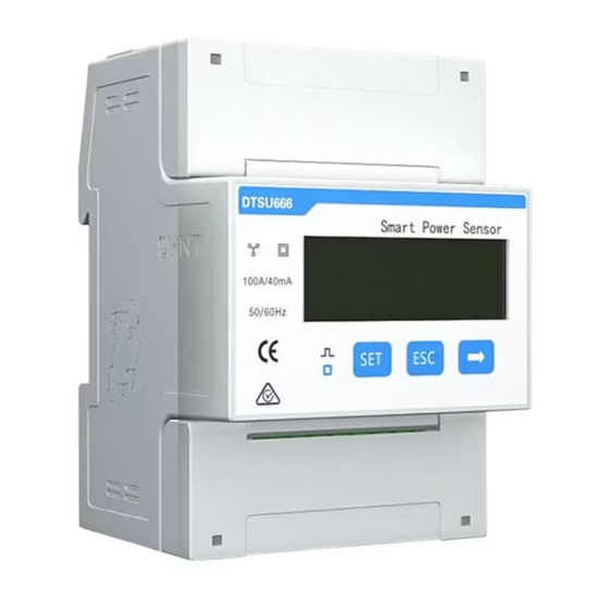
- Page 2 Overview Dimensions DTSU666-FE The dimensional tolerance is ± 1 mm . Appearance Specifications on the front panel Nameplate...
- Page 3 Key Specifications DTSU666-FE Category Input voltage 230V AC / 400V AC, 50Hz/60Hz Input current External current transformer: 100A/40mA Auxiliary power 85V ~288V AC/DC Class 1 (error within ± 1%) Electricity metering accuracy Power grid system Three-phase four-wire /Three-phase three-wire /One-phase one-wire...
-
Page 4: Installing Cables
Installing the DTSU666-FE Install the Smart Power Sensor on the standard guide rail of DIN 35mm. Press the Smart Power Sensor downwards onto the guide rail, then push it in place along the guide rail. Installing Cables Preparing Cables Cross-sectional... - Page 5 Connection Through Current Transformer and Direct Connection • Three-phase four-wire(Set Net:n34) 1. It is recommended to add a fuse on the voltage signal line. Please set the parameters after cable connections are complete. For details, see section 4 "Display and Parameter Settings".
- Page 6 • Three-phase three-wire(Set Net:n.33) 1. It is recommended to add a fuse on the voltage signal line. Please set the parameters after cable connections are complete. For details, see section 4 "Display and Parameter Settings".
- Page 7 • Three-phase three-wire(Set Net:n.34) 1. It is recommended to add a fuse on the voltage signal line. Please set the parameters after cable connections are complete. For details, see section 4 "Display and Parameter Settings".
- Page 8 • One-phase One-wire (Set Net:n34) 1. It is recommended to add a fuse on the voltage signal line. Please set the parameters after cable connections are complete. For details, see section 4 "Display and Parameter Settings".
- Page 9 Display and Parameter Settings Display The button → is used to switch the displays. Set parameter disp to enable the rotation display function. Display interface Instruction Display interface Instruction DHCP service, Imp. Active energy Yes:Enable =10000.00kWh no: disable Exp. Active energy Sensor IP1:192 =2345.67kWh Serial communication...
- Page 10 Parameter Settings Parameters Value range Indcation Current transformation ratio, used to set the current transformation ratio of input circuit: When connected through current transformer, CT= primary 0.1~6553.5 current / secondary current; When directly connected, CT shall be set to 1. Voltage transformation ratio, used to set the voltage transformation ratio of input circuit: When connected through voltage transformer, PT= primary...
- Page 11 Parameter settings Button description: SET means "confirm" or "cursor move" (when inputting numbers or parameters), ESC means "exit", and → means "add".The default user password is 701. • Set the current or voltage transformation ratio : • Set communication address or baud rate : •...
-
Page 12: Troubleshooting
• Modify user password : Troubleshooting Troubleshooting Method Symptom Cause Analysis 1. The voltage supplied to the sensor 1. Supply the correct voltage No display after power-on is abnormal. based on the specifications. 1. Check the network cable is 1. The network cable is not plugged in Abnormal ethernet plugged in and the network properly. -
Page 13: Customer Service Contact
Customer Service Contact Customer Service Contact Region Country Email France Germany Spain Italy 0039 3896692658 Europe hongys@chintglobal.com 0086 15000770865 Netherlands Other countries...
Need help?
Do you have a question about the DTSU666-FE and is the answer not in the manual?
Questions and answers