Table of Contents
Advertisement
Quick Links
Advertisement
Table of Contents

Related Manuals for SPX Cincinnati Fan Arrangement 9


Summary of Contents for SPX Cincinnati Fan Arrangement 9
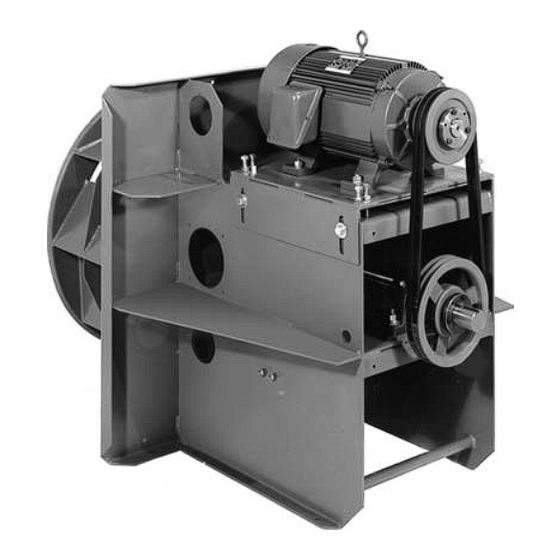
- Page 1 CINCINNATI FAN u s e r m a n u a l Arrangement 9 centrifugal fan Models CPF - CPAF I N STA L L AT I O N - O P E R AT I O N - M A I N T E N A N C E CF-11-IOM-24 ISSUED 3/2024 READ AND UNDERSTAND THIS MANUAL PRIOR TO OPERATING OR SERVICING THIS PRODUCT...
- Page 2 overview Read entire manual, including “Initial Unit Startup” before attempting to Note install and operate this equipment. Specifications Serial Number Mfg Date Note: The serial number above is a required reference for ant assistance. It is stamped on the lower nameplate. Blower Specifications Model Arrangement...
-
Page 3: Table Of Contents
contents This manual contains vital information for the proper installation and Note operation of your blower fan. Carefully read the manual before installa- tion or operation of the blower fan and follow all instructions. Save this manual for future reference. General ................................ -
Page 4: General
general Receiving Unpacking Be careful not to damage or deform any parts of the blower when removing it from the packaging container. All the packaging material should be kept in the event the blower needs to be returned. Handling Handling of the blower should be performed by trained personnel and be consistent with all safe handling practices. - Page 5 general Never operate a blower with a non-ducted inlet and/or discharge. If the Caution blower inlet and/or discharge is non-ducted, it is the users responsibility to install an inlet and/or discharge guard. Temperature Many blowers, blower components and all motors operate at temperatures that could burn someone if they come in contact with them.
-
Page 6: Installation
installation Installation Vibration Before any mounting method is selected, the user should be aware of the ef- fects vibration will have on the blower, motor and other parts. Improper blower installation can cause excessive vibration causing premature wheel and/or motor failure, that is not covered under warranty. Vibration eliminator pads, springs or bases should be properly installed to prevent any blower vibration from transmitting to the foundation or support structure. -
Page 7: Safety Guards
installation Plug fans are shipped with an inlet bell, but it is the users responsibility to provide the mounting structure and hardware to mount the bell. In most cases, the inlet bell mounting structure is an internal wall or plenum. The wall or plenum must be parallel with the mounting structure the blower is bolted to, to maintain the correct wheel-to-inlet bell clearance shown in Table 1. -
Page 8: Set Screw And Taper-Lock Bushing Torque
installation Set Screw and Taper-Lock Bushing Torque Values All blower wheel set screws are tightened to the proper torque prior to ship- ment. Some wheels may have taper-lock hubs and split, taper-lock bushings to secure the wheel to the blower shaft. Check all set screw or taper-lock bushing torques. -
Page 9: V-Belt Drives
installation V-Belt Drive If Cincinnati Fan supplied the belts and sheaves (drives package), they were carefully selected for the specific operating conditions supplied to us by the customer. Changing any of the v-belt drive component selections, supplied with the Warning blower, could result in unsafe operating conditions which could cause equipment failure, personal injury and death. - Page 10 installation Assembly 1. Remove belt guard and open shaft access holes. Remove the protective coating from the blower and motor shafts. 2. Loosen (don't remove) the four bolts in the side of the motor adjustment base. Now you can adjust the centerline height of the base by turning the four bolts in the top of the adjustment base, next to the motor feet.
- Page 11 installation Before attempting steps 12 and 15, make sure the area around the blower Caution is safe and secured so no one can get near the blower and possibly get injured when it is started. 12. Unlock power to the motor and run the blower for 15-20 minutes to allow belts to “seat”...
-
Page 12: Electrical
installation Electrical Disconnect Switches: All blower motors should have an independent disconnect switch located in close visual proximity to turn off the electrical service to the blower motor. Disconnects must be locked out in accordance with OSHA “lock out-tag out” procedures any time inspection or maintenance is being performed on the blower and/or motor assembly. - Page 13 4. Location: If the motor will be outside and subjected to the weather, it is recommended that a weather cover be installed to keep rain and snow off of the motor. No motors are guaranteed to be “watertight”. Be careful to allow enough openings between the motor and the motor cover to let the motor ”breath”.
-
Page 14: Maximum Speed And Speed Controllers
installation and T code of an EXP motor must be selected based on the atmosphere and/or environmental conditions the motor will be operating in. Consult the NEC (National Electric Code) and the NFPA (National Fire Protection Association) for the proper EXP motor Class, Group and T Code required for your specific application and location. -
Page 15: Initial Unit Startup
operation Pre-Startup and Post-Startup Check (Check blocks as each step is completed. Retain for you records) Failure to complete and document all the following Pre-Startup checks, Note Post-Startup checks and Vibration checks, could void all warranties. Pre-Startup Check completed by: Date Eight Hour Post-Startup Check completed by: Date... - Page 16 operation Blower Sheaves Figure 5 Clockwise (CW) Rotation Counter-Clockwise (CW) Rotation Pre-Startup Check completed by: Date Eight Hour Post-Startup Check completed by: Date Three-Day Post-Startup Check completed by: Date Apply power to the motor and let it come up to full speed. Turn off the power. Look and listen for any n n n n n n unusual noise or mechanical abnormality while the blower wheel is still spinning.
-
Page 17: Vibration
operation Vibration The blower was balanced at the factory to comply with ANSI/AMCA Stan- dard 204-05, Category BV-3. However, rough handling in shipment and/or erection, weak and/or non-rigid foundations, and misalignment may cause a vibration problem after installation. After installation, the vibration levels should be checked by personnel experienced with vibration analysis and vibration analysis equipment. - Page 18 operation Table 4 — Vibration Meter Probe Positions A—Pre-Startup Check completed by: Date B—Eight Hour Post-Startup Check completed by: Date C—Three-Day Post-Startup Check completed by: Date Alarm, rigid mount (.40) Alarm, rigid mount (.25) Figure 9 Vibration Severity Graph...
-
Page 19: Routine Inspection And Maintenance
maintenance Routine Inspection and Maintenance Periodic inspection of all the blower parts is the key to good maintenance and trouble-free operation. The frequency of inspections must be determined by the user and is dependent upon the severity of the application, but, it should never exceed a 12 month period. -
Page 20: Wheel Balance
maintenance For high temperature applications that require high temperature grease in Note the blower bearings, a chart similar to below will also specify that Only Dow Corning DC44 (silicone based) high temperature grease should be used. Do not over grease the blower bearings. Generally, 1-2 shots should be enough. Use a hand-operated grease gun at no more than 40 psi. -
Page 21: Vibration
maintenance Airstream material or chemicals can cause abrasion or corrosion of the blower parts. This wear is generally uneven and, over time, will lead to the wheel becoming unbalanced causing excessive vibration. When that happens, the wheel must be rebalanced or replaced. Other airstream components should also be inspected for wear or structural damage and cleaned or replaced if necessary. -
Page 22: Blower Shaft Or Bearing Replacement
maintenance Blower Shaft and Bearing Replacement The blower shaft and bearings for Cincinnati Fan blowers are carefully selected to match the maximum load and operating conditions for each specific blower model. If the instructions in this manual and those provided by the bearing manufacturer are followed, you should not need to replace the bearings for many years. - Page 23 maintenance 17. Remove the hardware holding the bearings on the shaft and then, remove the bearings from the shaft. 18. When replacing the bearings, we strongly recommend also replacing the blower shaft. However, if using the same shaft, file down all set screw marks on the shaft from the bearings, blower wheel or sheave.
-
Page 24: Safety Equipment And Accessories
maintenance 32. Install new set screws into the wheel hub, or new bolts into the taper-lock hub. Do not use old set screws or bolts. 33. Install the blower wheel onto the shaft making sure it is located on the shaft per the dimension you took in Step 4. -
Page 25: Ordering Replacement Parts
maintenance Replacement Parts Under normal conditions, you should not need any spare or replacement parts for at least 24 months after shipment from Cincinnati Fan. That does not include any wear due to abrasion, corrosion, excessive temperatures, abuse, misuse, accident or any severe conditions the fan was not designed for. •... - Page 26 troubleshooting Trouble Cause Loose mounting bolts, set screws or taper-lock hub bolts, bearings and sheaves Misalignment of sheaves, blower bearings or motor Worn or corroded blower wheel Accumulation of foreign material on blower wheel Bent motor or blower shaft Excessive Vibration Worn motor and/or blower bearings Worn sheaves and/or belts Motor out of balance...
-
Page 27: Long Term Storage
information Long Term Storage Storage exceeding 30 days after receipt of equipment. Failure to adhere to these instructions voids all warranties in their entirety. Note • Storage site selection: - Level, well-drained, firm surface, in clean, dry and warm location. Minimum temperature of 50°F (10°C). - Page 28 information • General Motor Procedure: If the motor is not put into service immediately, the motor must be stored in a clean, dry, warm location. Minimum temperature of 50°F. (10°C,). Several precautionary steps must be performed to avoid motor damage during storage. - Use a “Megger”...
-
Page 29: Warranty, Limits Of Liability, Responsibility And Returns
information Limited Warranty Cincinnati Fan and Ventilator Company (Seller) warrants products of its own manufacture, against defects of material and workman-ship under normal use and service for a period of eighteen (18) months from date of shipment or twelve (12) months from date of installation, whichever occurs first. This warranty does not apply to any of Seller’s products or any part thereof which has been subject to extraordinary wear and tear, improper installation, accident, abuse, misuse, overloading, negligence or alteration. - Page 30 information Limitation of Liability Notice of any claim, including a claim for defect in material or workmanship, must be given to Seller in writing within 30 days after receipt of the equipment or other products. Seller reserves the right to inspect any alleged defect at Purchaser’s facility before any claim can be allowed and before adjustment, credit, allowance replacement or return will be authorized.
-
Page 31: Parts Drawing
information Disclaimer This manual, and all its content herein, is based on all applicable known mate- rial at the time this manual was created. Any parts of this manual are subject to change at any time and without notice. If any statements, diagrams and/or instructions contained herein, for compo- nents not manufactured by the Seller, conflict with instructions in the manu- facturer’s manual (i.e.: motors, bearings, dampers, etc.), the instructions in the manufacturer’s manual, for that component take precedent. - Page 32 U S E R M A N UA L SPX ENGINEERED AIR MOVEMENT CF-11-IOM-24 ISSUED 3/2024 ©2024 SPX ENGINEERED AIR MOVEMENT ALL RIGHTS RESERVED 7697 SNIDER ROAD In the interest of technological progress, all products are subject to design T E C H N O L O G I E S MASON, OH 45040 USA and/or material change without notice.
Need help?
Do you have a question about the Cincinnati Fan Arrangement 9 and is the answer not in the manual?
Questions and answers