Table of Contents
Advertisement
Quick Links
Advertisement
Table of Contents

Related Manuals for Alpha BBS-012

Summary of Contents for Alpha BBS-012
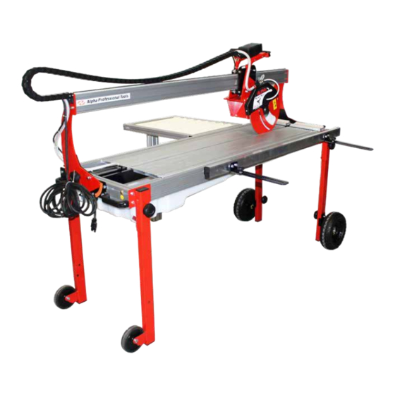
- Page 1 MANUAL Alpha Black Belt Rail ® Saw Instruction Manual * Shown with optional 8-roller table exten- sion(BBS8ROLL) & Side Countercut (BBSUSIDE) Part No: BBS-012 Version 06/2024 16 Park Dr Ste 9, Franklin, NJ 07416 • 800-648-7229 www.alpha-tools.com...
-
Page 2: Table Of Contents
TABLE OF CONTENTS 1 - INTRODUCTION ........................4 1.1 – About the Symbols ..........................4 1.2 – Manufacturer and Machine Identification ..................4 2 - TECNICAL INFORMATION ..........................5 2.1 – General Machine Description......................5 2.2 – Technical Data ............................6 2.3 – Noise Level .............................7 2.4 –... - Page 3 6.3 – Start / Stop ............................16 6.4 – Filling And Emptying The Water Tank ..................17 6.5 – Machine Usage ............................17 6.5.1 – Straight Cut ............................18 6.5.2 – Diagonal Cut .............................19 6.5.3 – Setting For 45 Degree Cut ......................21 6.5.4 – Hole Cut .............................22 6.6 –...
-
Page 4: Introduction
1. INTRODUCTION GENERAL INFORMATION Thank you for purchasing the Alpha Black Belt Wet Rail Saw for large format tiles (BBS-012). Professional Quality ® Rail Saw, Ideal for Cutting Ceramics, Porcelain, Glass Panel and other Materials. Please read this instruction manual thoroughly to ensure safe and correct use of the electric wet saw. -
Page 5: Tecnical Information
2 - TECHNICAL INFORMATION 2.1 – General Machine Description • The cutting machine, henceforth machine, has been designed and built to perform cutting and mitering on tiles for wall coverings and flooring prior to laying, and cutting bricks, stones and porcelain materials. •... -
Page 6: Technical Data
2.2 – Technical Data Physical sizes Weight (lbs / kgs) 231 lbs (105 kgs) Size A (in. / mm) 80.70 in (2050 mm) Size B (in. / mm) 29.53 in (750mm) Size C (in. / mm) 57.09 in (1450mm) Cut Specifications Blade diameter (in. -
Page 7: Noise Level
2.3 – Noise Level Ear-muff protection is compulsory. Caution - Warning The table below reports noise levels depending on operative condition and measurement points. This measurement was performed in respect of CEE rules 89/392, 91/368, ISO 3746. Lw - Sound power level ..........................96 dB (A) Leq - Equivalent sound pressure level at operator’s ear ................. -
Page 8: Safety Information
3 - SAFETY INFORMATION 3.1 – General • During the design and construction phase the manufacturer paid special attention to issues that may cause safety hazards to the health of people interacting with the machine. In addition to complying with all relevant laws, they have adopted all relevant “engineering rules and best practices”. -
Page 9: Safety Label Description
3.3 – Safety label description Some of these signals are applied to the machine, their position is indicated in the paragraph “Safety Labels Positions”. Upper limbs cut danger: The diamond blade has sharp edges. General danger: Before performing any maintenance, disconnect the power supply connector. -
Page 10: Perimetric Work Areas
3.5 – Perimeter Work Areas The picture shows operative areas: 1. Command area of the operator 2. Perimetric area 3. Dangerous area 3.6 – Safety Labels Position The illustration shows the position of the safety labels. Their meaning is explained under: “Safety labels description.”... -
Page 11: Accessories Installation
For this kind of operation, please proceed as follows: 1. Lift the machine as you can see in the picture. 2. Unscrew (A) knob, lower (B) support-foot and retighten the knob. 3. Repeat the same operation for all feet. 4. Lay the machine on the floor. 5. -
Page 12: Blade Replacement
4.3 – Blade Replacement Please proceed as follows: 1. Remove the (C) screws and remove the (B) disk protection. 2. Unscrew the (D) nut (Using provided Wrench and Hex Wrench). 3. Remove the (E) cutting blade and replace it. Remember to check rotation’s direction. 4. -
Page 13: Electrical Connection
4.4 – Electrical Connection 1. It is recommended to install a circuit breaker (A) upstream from the machine power supply. 2. Connect the electrical plug to the plant’s mains supply . 3. Connect the ground cable to the (B) ground terminal on the machine. Check that line voltage (V) and frequency (Hz) correspond to those of IMPORTANT the machine (see nameplate and wiring diagram). -
Page 14: Tuning Information
2. Loosen and slide the Knob Bolt into the Locking Bracket position. Re-tighten the Knob Bolt to secure the Cutting Head for transportation. 5 – TUNING INFORMATION 5.1 – Tuning Recommendations Before doing any work or taking any action on the machine, always turn main IMPORTANT power OFF. -
Page 15: Setting The Cutting Angle
5.3 – Setting the Cutting Angle Please proceed as follows: 1. Loosen the (A) knob. 2. Rotate the (B) goniometer until reaching the desired angle value. 3. Re-tighten the (A) knob at the end of the operation. 4. Adjust the position of the (C) stopper adapting it to cut material size. 5.4 –... -
Page 16: Usage
6 – USAGE 6.1 – Recommendation For Usage And Operation The incidence of accidents resulting from the use of machines depends on many factors that are not always can be prevented and controlled. Some accidents can be caused by environmental factors not predictable, others strongly dependent on user behaviour. -
Page 17: Filling And Emptying The Water Tank
6.4 – Filling and emptying the water tank Filling 1. Make sure the (A) tank cap is screwed in tight. 2. Remove the (B) working table. 3. Put water into the tank until the pump is fully submerged (C). Emptying 4. -
Page 18: Straight Cut
6.5.1 – Straight Cut 5. Remove the (A) knob 6. Loosen the (B) knob and bring the cutting group in its full-lowered position. 7. Re-tighten the (B) knob Adjust cut width following the job’s needs (See: “Setting the Cutting Width”). Place the tile on the working table against the (C) guide. -
Page 19: Diagonal Cut
7. Apply hand pressure on the tile and block it on the top. 8. Turn the (E) switch on (pos. I) to activate (F) cutting blade rotation. 9. Adjust the (R) tap to optimize water’s flow. 10. Grasp the (G) handle and slowly bring the cutting group forward (H). 11. - Page 20 4. Adjust cut width following the job’s needs (See: “Setting the Cutting Width”). 5. Place the tile on the working table, against the (C) guide. 6. Place the (D) goniometer against the tile. Apply hand pressure on the tile and block it on the top. Press the (E) switch (pos.
-
Page 21: Setting For 45 Degree Cut
6.5.3 – Setting for 45 Degree Cut 1. Remove the (A) knob 2. Loosen the (B) knob and bring the cutting group down until the blade’s lower rim plunges just below the table surface. Re-tighten the (B) knob. 3. Loosen both symmetrical lock knobs (C) and tilt the upper part of the machine (bridge + cut head) (D) on its side. Re-tighten the (C) knobs. -
Page 22: Hole Cut
7. Apply right hand pressure on the tile and block it on the top. 8. Turn the (E) main switch onto (pos. I) and blade’s rotation will start (F). 9. Adjust the tap to optimize water’s flow. 10. Grasp the (G) handle and, slowly, bring the cutting group forward (H). 11. - Page 23 2. Loosen the (A) knob move the cutting group in its desired position, then retighten the (A) knob. 3. Loosen the (B) knob to allow for vertical cutting group movement. 4. Lay the (C) tile onto the work table resting it against the base reference guide. 5.
-
Page 24: Long Inactivity
6.6 – Long inactivity In case the machine remains inactive for a long time, please proceed as follow: • Perform all maintenance operations. • Perform a general cleansing. • Watch over the electrical contacts using an antioxidant spray. • Put the machine in a sheltered place, accessible only by authorized personnel. 7 –... -
Page 25: Sliding Wheels' Adjustment
7.3 – Sliding Wheels’ Adjustment Please proceed as follows: 1. Loosen both (A) nuts locking the two wheels installed under the cut group. 2. Turn both eccentric (B) hexagonal screw until both (C) wheels are perfectly pressed against the rail. 3. -
Page 26: Blade Perpendicularity Adjustment
7.5 – Blade perpendicularity adjustment For this Operation please proceed as follows: 1. Remove blade protection as explained at point 4.7. 2. Place a square (B) on the working table and against the cutting blade (C) in order to check blade perpendicularity. 3. -
Page 27: Attaching The Tire Wheel
Inconvenient Cause Action Make sure power connector is firmly plugged IN Machine does not start Power supply circuit fault Check electrical system efficiency Check switch breaker operation Make sure power connector is firmly plugged IN Machine stops Power supply circuit fault Check electrical system efficiency Call customer service Wrong installation... - Page 28 16 Park Dr Ste 9, Franklin, NJ 07416 • 800-648-7229 www.alpha-tools.com Copyright © 2024 Alpha Professional Tools. All rights reserved. 06/2024...
Need help?
Do you have a question about the BBS-012 and is the answer not in the manual?
Questions and answers