Table of Contents
Advertisement
Quick Links
Advertisement
Table of Contents

Related Manuals for NCR N4000


Summary of Contents for NCR N4000
- Page 1 User Guide NCR N4000 Site Controller (1659) Release 1.0 BCC5-0000-5320 Issue B...
- Page 2 NCR, therefore, reserves the right to change specifications without prior notice. All features, functions, and operations described herein may not be marketed by NCR in all parts of the world. In some instances, photographs are of equipment prototypes. Therefore, before using this document, consult with your NCR representative or NCR office for information that is applicable and current.
- Page 3 Notice: This document is NCR proprietary information and is not to be disclosed or reproduced without consent. Safety Requirements The NCR N4000 Site Controller conforms to all applicable legal requirements. To view the compliance statements, see the NCR HSR Servers Safety and Regulatory Statements (BCC5-0000-5096).
- Page 4 240 V. Moisture The N4000 is not water-resistant. The N4000 should not be sprayed directly, as the force of pressurized water could potentially invade the enclosure through the enclosure grille or cooling vents. Accordingly, N4000 units should not be installed in areas where they might be exposed to direct water spray.
- Page 5 Power Supply Cord Used as Disconnect Means Warning: The power supply cord is used as the main disconnect device. Ensure that the socket outlet is located/installed near the equipment and is easily accessible. Attention: Le cordon d'alimentation est utilisé comme interrupteur général. La prise de courant doit être située ou installée à...
- Page 6 Warning: Grounding circuit continuity is vital for safe operation of the machine. Never operate the machine with the grounding conductor disconnected. Instruction pour Conducteurs Au cas d’un mauvais fonctionnement ou d’une panne, le conducteur de protection offre une alternative de résistance au courant électrique, permettant de réduire le choc. Ce produit est équipé...
- Page 7 NCR is not responsible for any radio or television interference caused by unauthorized modification of this equipment or the substitution or attachment of connecting cables and equipment other than those specified by NCR.
- Page 8 This device has been tested and found to comply with the limits for a Class A digital device, pursuant to the Australian/New Zealand standard AS/NZS 3548:1995 (Deviation for CE’s EN55022). International Radio Frequency Interference Statement Warning: NCR N4000 Terminals are Class A products. In a domestic environment these products may cause radio interference.
- Page 9 If you do not have access to a computer, you may leave a voice message at: 1-800-528- 8658 (USA), or (International) +1-770-623-7400. When leaving a message, please provide a phone number and/or an email address so NCR can contact you if additional details are needed.
- Page 10 • Description of the problem, including any system error codes, error condition, or guidance to the area of failure. The NCR Agent will provide you with a work order number, which serves as your Return Material Authorization (RMA). Please provide the RMA on the outside of the shipping box.
-
Page 11: Table Of Contents
Table of Contents Chapter 1: Product Overview Introduction Features and Benefits Technical Specifications Hardware Design and Components External Connectors Mounting Options Installation Notes Chapter 2: Installing the Site Controller Safety Precautions Installation Procedures Connecting Peripherals Keyboard Mouse Monitor Printer Microphone and Speakers Connecting to a Network Connecting to a Power Source Chapter 3: Using the Site Controller... - Page 12 Updating the BIOS using the Windows Flash Executable Pack- Updating through the .exe File Updating through the Unattended Mode Updating the BIOS using a USB Memory Key Cleaning the Site Controller...
- Page 13 Revision Record Issue Date Remarks Feb 2019 First Issue Apr 2019 Added a warning referring to the power supply that can be used with N4000...
-
Page 15: Chapter 1: Product Overview
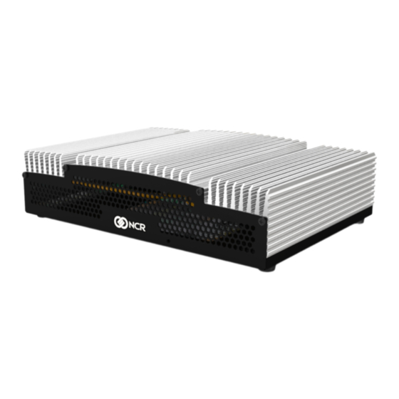
Chapter 1: Introduction The NCR N4000 Site Controller is a small form factor, solid–state, back of house site controller that is designed and built for best in class reliability. The N4000 uses solid state drives (SSD) storage, a passively cooled heat spreading enclosure, and low power,... -
Page 16: Features And Benefits
Product Overview Features and Benefits Features Benefits ® Intel Core™ The fast performance, low thermal processor using multi–core i5-8500T Processor technology makes it possible for advancements on multi– threaded applications and multitasking. Dual Independent Two (2) Display Port connections allow for two simultaneous Digital Displays independent displays. -
Page 17: Technical Specifications
Product Overview Technical Specifications • Support for Intel LGA 1151 processor Intel 8th Generation Coffee Lake-S core ® • Intel Core™ i5-8500T Processor (9M Cache, up to 3.50 GHz, Hexa–core) Volatile Memory • Two 260–pin DDR4 2400/2133 MHz Non ECC, unbuffered memory • Dual Channel Memory architecture •... - Page 18 Product Overview Operating 0 to 40°C (32 to 104°F) Temperature Storage -40 to 85°C (-40 to 185°F) Temperature Note: The unit must be in its original pack material in humidity controlled environment. Humidity 0 to 90% non–condensing Environmental ROHS, WEEE compliance EMI Certifications FCC Class A, CE...
-
Page 19: Hardware Design And Components
Product Overview Hardware Design and Components External Connectors Item Definition Serial port, 9–pin DB9 full RS232 port Microphone in Analog Line out USB 3.1 high–current dual stack ports Ethernet port, 8-pin RJ45 10/100/GbE Ethernet port, 8-pin RJ45 10/100/GbE – Intel AMT Display port Display port USB 3.1 ports... -
Page 20: Mounting Options
Product Overview Mounting Options The NCR N4000 Site Controller can be mounted in the following ways: • Counter Top Mounting—requires no additional hardware • Wall Mounting—requires Mount Bracket kit (1659-K001) • Rack Mounting—requires Mount Bracket kit (1659-K001) -
Page 21: Installation Notes
Product Overview Installation Notes Footprint: The N4000 requires a clearance of 2.0 in. (5.1 cm) above, behind, and to the sides to properly install the unit. This accommodates the unit along with its associated cable connectivity and provides for proper ventilation. -
Page 22: Chapter 2: Installing The Site Controller
Chapter 2: Safety Precautions To ensure the safe use of the NCR N4000, observe the following precautions: • To avoid a possibility of electrical shock, be sure to connect the power cord to the Site Controller before connecting it to the main power supply. -
Page 23: Installation Procedures
Installation Procedures Note: This section discusses the procedure for installing the NCR N4000 Site Controller on a counter top. For Rack and Wall Mount installation configurations, refer to N4000 Mount Kit Instructions (1659-K001). To install the N4000, do the following: 1. -
Page 24: Connecting Peripherals
A mouse permits users to interact with your operating system and installed software. To connect a mouse to the N4000, do the following: • Connect the mouse to any of the USB ports on the back panel of the N4000. For more information on the IO ports, refer to External Connectors on page 5. -
Page 25: Printer
To connect a printer to the N4000, do the following: • Connect the printer to one of the USB ports on the back panel of the N4000. For more information on the IO ports, refer to External Connectors on page 5. -
Page 26: Connecting To A Power Source
For international configurations, the country specific power cord may be ordered separately. • To connect the N4000 to a power source, connect the power supply cable to the 4-pin power DIN connector on the back panel of the N4000 and then connect the power supply to an AC wall outlet. -
Page 27: Chapter 3: Using The Site Controller
Source on page 12. To start up the N4000, do the following: • Press the Soft Power Switch on the back panel of the N4000. The blue PWR status LED (below the power switch) then lights up. Shutting Down To shut down the N4000, do the following: •... -
Page 28: Activating/Deactivating The Second Lan
3-14 Using the Site Controller Activating/Deactivating the Second LAN To disable the integrated Network Adapter, do the following: 1. From the Windows taskbar, select Start→Control Panel. 2. From the Control Panel items, select Device Manager. 3. In the Device Manager window, expand Network adapters. A list of available network connections is then displayed. - Page 29 Using the Site Controller 3-15 5. Select Yes. After a few seconds, the window will refresh and the selected network adapter should now appear as disabled. Note: The disabled card will still be visible when viewing network connections and the Device Manager. Performing these steps will allow only one network connection to be visible from the operating system.
-
Page 30: Updating The Bios
Using the Site Controller Updating the BIOS The BIOS is located in the Serial Peripheral Interface (SPI) chip on the processor board. The software update is distributed through the NCR website. The BIOS update can be performed using any of the following options: •... -
Page 31: Downloading The Bios Update
Using the Site Controller 3-17 Downloading the BIOS Update 1. Go to the NCR support website http://www5.ncr.com/support/support_drivers_ patches.asp. 2. Select Hospitality Support Files (Drivers, Firmware, Operating Systems, Platform Software, BIOS, etc.). The following page is then displayed. - Page 32 3-18 Using the Site Controller 3. Under Servers, select N4000. The list of available BIOS for N4000 is then displayed. 4. Select the BIOS to download. 5. Follow on–screen instructions to download the files.
- Page 33 Updating through the .exe File Note: Ensure that no other programs are running while the BIOS update is in progress. 1. Download the Windows Flash Executable package from the NCR website. For more information, refer to Downloading the BIOS Update on page 17.
- Page 34 3-20 Using the Site Controller Updating the BIOS using a USB Memory Key 1. Download the Windows Executable package from the NCR website. For more information, refer to Downloading the BIOS Update on page 17. 2. Extract the files to the USB key.
Need help?
Do you have a question about the N4000 and is the answer not in the manual?
Questions and answers