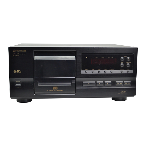
Pioneer PD-F607 Service Manual
File-type cd player
Hide thumbs
Also See for PD-F607:
- Service manual (35 pages) ,
- Operating instructions manual (31 pages) ,
- Operating instructions manual (20 pages)
Advertisement
Quick Links
FILE-TYPE CD PLAYER
PD-F607
PD-F507
Refer to the service manual RRV1877 for PD-F607/KUXJ and
PD-F507/KUXJ.
THIS MANUAL IS APPLICABLE TO THE FOLLOWING MODEL(S) AND TYPE(S).
Model
Type
PD-F607
WYXJ
O
WVXJ
O
WPWXJ
MAMXJ
RLXJ
RDXJ
PIONEER ELECTRONIC CORPORATION
PIONEER ELECTRONICS SERVICE, INC. P.O. Box 1760, Long Beach, CA 90801-1760, U.S.A.
PIONEER ELECTRONIC (EUROPE) N.V . Haven 1087, Keetberglaan 1, 9120 Melsele, Belgium
PIONEER ELECTRONICS ASIACENTRE PTE. LTD. 501 Orchard Road, #10-00 Lane Crawford Place, Singapore 0923
C C C C C
PIONEER ELECTRONIC CORPORATION 1998
Power Requirement
PD-F507
AC220-240V
AC220-240V
O
AC220-240V
O
AC220-230V
O
AC110-120V/220-240V
O
AC110-127V/220-240V
CONTENTS
1. SAFETY INFORMATION .................................... 2
2. CONTRAST OF MISCELLANEOUS PARTS ..... 3
3. SCHEMATIC AND PCB DIAGRAMS ................. 8
4-1, Meguro 1-Chome, Meguro-ku, Tokyo 153-8654, Japan
RRV1951
The voltage can be converted by
the following method.
With the voltage selector
With the voltage selector
T–ZZY APR. 1998 Printed in Japan
ORDER NO.
Advertisement

Related Manuals for Pioneer PD-F607


Summary of Contents for Pioneer PD-F607
- Page 1 PIONEER ELECTRONICS SERVICE, INC. P.O. Box 1760, Long Beach, CA 90801-1760, U.S.A. PIONEER ELECTRONIC (EUROPE) N.V . Haven 1087, Keetberglaan 1, 9120 Melsele, Belgium PIONEER ELECTRONICS ASIACENTRE PTE. LTD. 501 Orchard Road, #10-00 Lane Crawford Place, Singapore 0923 C C C C C PIONEER ELECTRONIC CORPORATION 1998 T–ZZY APR.
-
Page 2: Safety Information
Improperly performed repairs can adversely affect the safety and reliability of the product and may void the warranty. If you are not qualified to perform the repair of this product properly and safely, you should not risk trying to do so and refer the repair to a qualified service technician. - Page 3 PD-F607, PD-F507 2. CONTRAST OF MISCELLANEOUS PARTS NOTES : ÷ Parts marked by “ NSP ” are generally unavailable because they are not in our Master Spare Parts List. ÷ The mark found on some component parts indicates the importance of the safety factor of the part.
- Page 4 Not used PNW2019 PNW2019 PNW2019 PNW2019 No.12 Note : The numbers in the remarks column correspond to the numbers on the exploded diagram, Refer to “EXPLODED VIEWS”. For ASSEMBLIES, Refer to “ CONTRAST OF PCB ASSEMBLES” and “3. SCHEMATIC AND PCB DIAGRAMS”.
-
Page 5: Exploded Views
Protecter R No.1 N0.13 Front Warranty Card Operating Instructions Control Cable No.3 Protecter F No.4 Protecter R Packing Case EXTERIOR and FRONT PANEL SECTION Rear Base No.6,No.8 Control Panel No.12 No.7 No.9 Foot No.11 Under Base No.10 Screw (BBZ30P060FMC) No.5... -
Page 6: Pcb Parts List
PD-F607, PD-F507 CONTRAST OF PCB ASSEMBLIES MOTHER BOARD ASSY ASSY ( For PD-F507 ) PWM2197, PWM2195 and PWM2196 are constructed the same except for the following : Part No. Symbol and Description Remarks Mark PWM2196 PWM2197 PWM2195 D391-D394 1SS254 Not used... - Page 7 PD-F607, PD-F507 Mark No. Description Part No. Mark No. Description Part No. Q151 2SA854S JA321 OPTICAL OUTPUT JACK TOTX178 Q403,Q404 2SD2144S TERMINAL 2P RKC-061 Q152 DTA124ES X401 CRYSTAL RESONATOR PSS1008 Q321,Q405 DTC124ES (16.9344MHz) MTZJ18B X351 CRYSTAL RESONATOR VSS1014 (4.194MHz) D218 MTZJ6.2B...
- Page 8 J801 D20PWW0545E RSG1030 CN701 J801 D751 SLR-342VCT31 POWER SW ASSY NOTE: The numbers marked with a circle show the number of each PWZ3623 measuring point,which correspond to the number in the service manual PD-F607 ( ORDER NO.RRV1877 ) on page16-17.
- Page 9 PD-F607, PD-F507 NOTE: When ordering service parts, be sure to refer to “PARTS LIST of EXPLODED VIEWS” or “PCBPARTS LIST”. IC301 (CXD2529Q) PIN No. 1 2to4 7 Voltage(V) 0.05 2.6-2.7 2.5 3.1 1.2-1.4 1.2-1.4 PIN No. 89,90 93to95 50to55 84to86...
- Page 10 PD-F607, PD-F507 PCB DIAGRAMS NOTE FOR PCB DIAGRAMS: 1. Part numbers in PCB diagrams match those in the schematic diagrams. HEADPHONE BOARD ASSY 2. A comparison between the main parts of PCB and schematic diagrams is shown below. Symbol in PCB...
Need help?
Do you have a question about the PD-F607 and is the answer not in the manual?
Questions and answers