
Related Manuals for Stortech SHC-20280C/I

Summary of Contents for Stortech SHC-20280C/I
- Page 1 DRIVER MONITORING SYSTEM (DMS) Installation and Programming Manual SHC-20280C/I Version1 11/2023...
-
Page 2: Table Of Contents
Contents Basic Features Disclaimer Product Features Stortech Electronics does its best to ensure the integrity and accuracy of the contents in this Packing List document and cannot guarantee this. The outcome of using this document shall be entirely Installation the user’s own responsibility. Stortech Electronics reserves the right to change the contents of Device component &... -
Page 3: Basic Features
Overview Features Basic Features Fatigue Driving Detection • • 2MP resolution CMOS Sensor Distraction Driving Detection (Line of Sight Deviation from Driving Direction) • • 2.8mm lens Abnormal Driving Behaviour Detection (Making Phone Call/Smoking) • • True Day/Night with ICR The detection function can still work normally even when the driver is wearing the •... -
Page 4: Installation
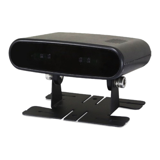
Installation DEVICE COMPONENT AND SYSTEM CONNECTION DMS Key Components Description IR Light blocking panel Built-in Speaker Micro SD card slot for video recording 4 * IR (94nm) LEDs Power indicator Built-in Camera The Wi-Fi hotspot of the device currently supports AP &... -
Page 5: Cable Connection Definitions
Overview Cable Connection definitions Cable 1 The left end of cable 1 connects to connecting terminal inside the DMS, the right end 4-PIN aviation female connector connects the monitor or external power cable (cable 3). 5-PIN aviation female connector connects cable 2, for leading to RS232 and CAN communication Cable 2 cable. -
Page 6: Dms Installation And Calibration
DMS INSTALLATION AND CALIBRATION The DMS needs to be installed on the dashboard away from the driver, between 0.8 ῀ 1.2m away and at an angle of about ± 30°. See Right. Once a suitable installation position has been located. Carry out the installation and calibration at the same time with the installer and driver. -
Page 7: Installation & Calibration Operation Procedures
Enter the URL http://192.168.60.1 on the mobile phone’s browser (or scan the QR code “Right. The browser will go to the log-in page “Right”. Press “login” to enter preview page and view the displayed video in real-time. P/W blank The maximum operating distance between the device and mobile phone is about by default After a successful connection, calibration and setup can begin. -
Page 8: Driver Monitoring Mode
Once the square box is green, the Engineer clicks the “Ok” button on the mobile. Start to calibrate as per the voice prompts. These may last 10-sec. During the calibration process, the driver must maintain their normal driving position and loo straight ahead. A voice prompt will indicate the start of calibration. -
Page 9: Distraction Driving Alarm
This alarm is based upon how open the driver’s eyes are. If the eyes close for > 3-Sec a fatigue detection alarm will be triggered. The threshold can be set in the webpage. Note. A “no Facemask Alarm” is off by default. Distraction Driving Alarm A Distraction Driving Alarm will be triggered if the driver’s head deviates left or right >... -
Page 10: Sunglasses Alarm
Sunglasses Alarm If the driver is detected wearing sunglasses for > 2-4 Sec the Sunglasses Alarm is triggered. No Seatbelt Alarm If the system detects that the driver is not wearing their seatbelt for > 10-Sec the No Seatbelt Alarm will be triggered. Smoking Alarm If the system detects that the driver is Smoking for >... -
Page 11: Yawn Alarm
Yawn Alarm The device triggers a Yawn Alarm is the system detects a driver yawning for > 2- 4 Sec. No Driver Alarm If the system detects that there is no driver in the driving seat for > 15-Sec the No Driver Alarm will be triggered. -
Page 12: Face Recognition System
Face Recognition System (FRS) The function of FRS is to detect whether the current driver is registered in the device (whether the driver is eligible to drive the vehicle), and then give an audible response. If an unregistered driver is detected, the detection cannot pass, and will make a 20-second video recording and send alarm data through RS232 and CAN interface. - Page 13 b. Delete – To delete a single driver, click the “Delete” button corresponding to the relevant driver. The driver’s face data will be deleted. To delete multiple drivers, click the “Batch Delete” button, click each driver to be deleted. Then click the “Batch Delete” button again. The driver’s face data will be deleted.
- Page 14 Driver Face Recognition Facial Recognition can be run in two-ways. 1. In Function Test mode. Click “login test” button see “Right”. 2. In Normal Operation mode. After the device reboots, the FRM will automatically rune (Ensure that FRM is turned on). Facial Recognition is the same as Registering a Face.
-
Page 15: Webpage Function Setting
Micro SD Card 8. Webpage Function Setting Switch information & Language video query Main Interface on the Webpage Parameter configuration Real-time display preview Refer to Refer to Chapter 7.2 for Chapter 6 for Calibration Query Function Status Query – Click the “Query Function” button on the main interface to access. -
Page 16: Parameter Configuration
Note: If “Normal” & “Picture” is clicked, a pop-up displaying “Normal Picture Query Is Not Supported” will appear. Video files are named after a combination of alarm-time and alarm type. Each video file can be downloaded locally, viewed on-line or replayed on a computer with an SD Card slot. - Page 17 Media Configuration Image Mirror Switch controls whether to turn on mirror image, the default is on. Image Flip Switch controls whether to turn on image flipping Mainstream/SubStream Able to set the parameters of Mainstream/SubStream/Picture /Picture stream/Display stream/Monitor display. stream Switch controls whether to turn on picture stream overlay and to display the time and channel.
- Page 18 Network Configuration Sever Config Configured switch can be either normally open/close server login function. Configuring server IP address and port number (183.233.190.23:9090, set this IDS server parameter based on your actual situations) can connect to the corresponding server’s CMS to view the real-time stream and device information. Server Select the connection mode to the server.
-
Page 19: System Function
NTP Time When selecting NTP Enable, the device date and time will be synchronized Configuration according to those on the NTP server. After setting the NTP synchronization interval, for example, 30 minutes, the device will synchronize itself with the NTP time when it is started, and every 30 minutes after that. - Page 20 • LAN mode Set “Server Network Type” to LAN, both dynamic and static IP addresses are supported. 1) Dynamic IP If DHCP server is available on a networking LAN, able to select DHCP option. The device will be assigned a networking IP. After the server login function is enabled, you can connect to the CMS of the corresponding server to view real-time streams and device information.
-
Page 21: Protocol
Protocol The device supports two types of protocols, RTSP and ONVIF. Note: When using a network cable, the computer needs to be configured with the same network address format as the device. • RTSP - Use video software to open RTSP stream. E.g. VLC: Connect the network cable and open the VLC, click Media->Open Network Streaming - >input “rtsp://IP/live/mainstream”,The "IP"... - Page 22 • ONVIF – Use the IP Camera Viewer or other software that supports the ONVIF protocol. Followings take IP Camera Viewer as an example. Ensure that the network has been connected, and follow steps in Figure 40: add new camera->input ipaddr ->test ipaddr-> OK. The Port number is 80 by default.
-
Page 23: Client Function
CMS Client Function a. VIEW information Real-time data Real-time image Click the device with online status (green), and right-click Open or Close the real-time stream. These four buttons can switch the number of channels to be viewed at the same time, and the default is the nine-split button. - Page 24 2. Real-time alarm When the device is online with CMS (green) and the driver triggers the alarm, an alarm window will pop up at the lower right corner of the computer display screen. If the alarm window is configured to close on the CMS, the alarm window is not displayed. For example, in CMS->Settings->...
- Page 25 Step 1:Click “Playback” to select the required equipment, and the information on the calendar will be updated accordingly, with a blue mark indicating that there is a video to watch back on this date. Step 2:Select the required date and time and click the “Search” button.
-
Page 26: Upgrade
b. Parameter configuration Select the online (green) device, right-click and click "Configuration" to open the configuration parameter page, where users can modify the parameters of the device, and the parameters of the device will also be modified accordingly. Upgrade The device version is updated in 4-ways: Local upgrade, Web page online upgrade, Online upgrade and Offline upgrade. - Page 27 b. Web page online upgrade Put the Micro SD card into the device card slot and enter the webpage through the network cable or device hotspot. Step 1: After logging onto the webpage, enter the "System" configuration page, click the “Add File” button to upload the upgrade package file or drag the upgrade package file to the designated area.
-
Page 28: Troubleshooting
Troubleshooting The following problems are not necessarily caused by equipment damage. When encountering similar situations, please check according to the following instructions and contact customer service for repair if the problem cannot be solved. Problems Possible Causes/Solutions Improper connection of device; It is likely an issue with the power supply, No picture, no ensure the device indicator is normal;... -
Page 29: Specification
Specifications GPS Module Option Mobile App LAN communication via ONVIF Protocol ENVIRONMENTAL SHC- Operating Temp/ Hum -20°C ~ +70°C /10-95% RH 20280C/I Storage Temp/Hum -40°C ~ +85°C /10-95% RH Vibration Resistant 5.9G (ISO 16750.3) VIDEO ELECTRICAL Imaging Device 1/2.9” Colour CMOS Sensor Power 10 - 32V DC, 5W Resolution... - Page 30 Whilst every effort has been made to ensure the accuracy of the information provided, no liability can be undertaken for any errors or omissions. All dimensions stated in this document are approximate. Stortech Electronics Ltd reserves the right to alter the specifications and introduce changes...
Need help?
Do you have a question about the SHC-20280C/I and is the answer not in the manual?
Questions and answers