
Related Manuals for Stortech SMF-1040/360T

Summary of Contents for Stortech SMF-1040/360T
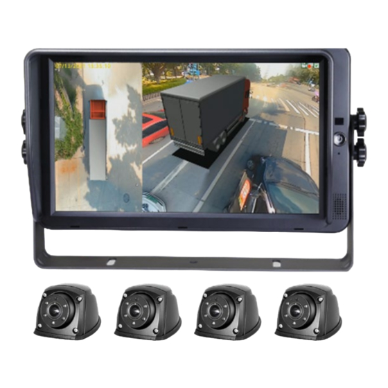
- Page 1 360° VEHICLE MONITORING SYSTEM Installation and Programming Manual SMF-1040/360T & SMF-0740/360T Version1 08/2023...
-
Page 2: Table Of Contents
Basic Features Product Features Disclaimer Packing List Stortech Electronics does its best to ensure the integrity and accuracy of the contents in this Installation document and cannot guarantee this. The outcome of using this document shall be entirely Connection Diagram the user’s own responsibility. -
Page 3: Basic Features
Overview Features Basic Features Panoramic image • • 7” & 10” 1024 x 600 HD Monitor options • Seamless image stitching • Integrates 360AVM Algorithm for panoramic Images. • 360° with no blind spots / Clear all-around view • Automatic calibration < 1Minute Auto-switch to reversing image when triggered –... -
Page 4: Installation
Installation Connection Diagram White 4P male for Camera 1. Blue 4P male for Camera 2. Green 4P male for Camera 3. Brown 4P male for Camera 4. Single red wire to power wire of DC: 10-32V. Single black wire to GND. Single white wire to positive power wire of Camera 1. -
Page 5: Ir Remote Control
Operation Instruction No index entries found. REMOTE CONTROLLER ENTER: To enter main menu or confirm menu selection. ESC: Exit main menu interface/return to main menu interface. LEFT/RIGHT: Left, Right /Minu, Plus button. Shift image channel left or right view or operate plus/minus in main menu interface. UP/DOWN: Front/Back button. -
Page 6: User Main Interface
USER MAIN INTERFACE User Setup: User settings to set up, Basic setup/ Display / Triger / Setup / Radar / Screen Setup • Storage: Storage management can check the SD storage and log file management. (Only for customers needing to format SD Card through USB). -
Page 7: Display
DISPLAY Display Setup • Blending Region: Overlapping On/Off • Instant Rear View: Default setting is ON. When set to Off, there will be a “splash” screen display before the panoramic view is shown. When set to On, a single view picture will be displayed in 3 sec before the panoramic view is shown. -
Page 8: Trigger
TRIGGER Trigger Setup • Trigger Priority: Trigger priority default value is None. When set to None; Panorama will display the first triggered view. E.G., when the rear (brown) wire is triggered, the rear-view camera is displayed in a panoramic view. At this point if the left road (white) wire is also triggered, the rear road camera is still displayed in panorama. -
Page 9: Radar
RADAR Radar setup interface • Category: Radar configuration. Radar not available when set to Off. (N.B. Ultrasonic sensors are currently unavailable). • Unit: Default unit value is Meter. Meter / Inch selectable. • Trigger Control: Trigger control setting. Default is On. When set to On, the sensor will respond only when the “back”... -
Page 10: Screen Setup Storage
SCREEN SETUP Screen Parameter Setup • Volume: Set screen volume (Not currently available) • Dimmer setup: Set screen brightness, users can select between Low, Middle, High and Auto. When set to Auto, the monitor auto backlite function will mean the monitor will turn bright in bright environments (Day mode) and darker in dim environments (Night mode). -
Page 11: Interface
Automatic Calibration • Cancel: Cancel button, click this to exit calibration interface • Calibrate: Automatic calibration button, click to enter automatic calibration mode. • Calibration Log: Displays calibration log. Precautions • Each camera should fully view the 2 nearby calibration mats and their view must not be blocked by any objects. -
Page 12: Calibration Image Export Import
Reminder • It is recommended to use the quad display screen to monitor the installation effect in real-time when the cameras are installed. It is required that the vehicle’s body can still be observed at the centre of each screen. •... -
Page 13: Surround View
Surround View Blending angle and surround view parameters setting • Blending Angle Setting: Blending angle of 4 corners can be set separately, range 0° ~ 90°. • Width Setting per Channel: Width value of 4 channels can be set separately. Unit can be inch / cm. Parking Line Reversing cursor adjustment interface. -
Page 14: Information
Information Current Version: Current Software version • Upgrade Configure: Configuration file upgrade. • • Upgrade: Version upgrade, select the version that needs to be upgraded and click the “upgrade” button. • System Setup: Reset: Reload default settings Import: Import the configuration file Export: Export configuration... -
Page 15: Specification
Mounting Bracket Yes, U-shaped made of metal Specifications Weight 0.4Kg MONITOR Dimensions 267 x 159 x 30mm LCD Size 10” CAMERA Resolution 1,024(H) X 600(V) 3(RGB) Imaging Device 1/2.9” CMOS Sensor Contrast 600:1 Resolution 1080P Maximum Brightness 600cd/m Min. Illumination Colour: 0.01Lux @ F1.2/ 0.0Lux Monochrome Response Time 10 - 15ms... - Page 16 Whilst every effort has been made to ensure the accuracy of the information provided, no liability can be undertaken for any errors or omissions. All dimensions stated in this document are approximate. Stortech Electronics Ltd reserves the right to alter the specifications and introduce changes...
Need help?
Do you have a question about the SMF-1040/360T and is the answer not in the manual?
Questions and answers