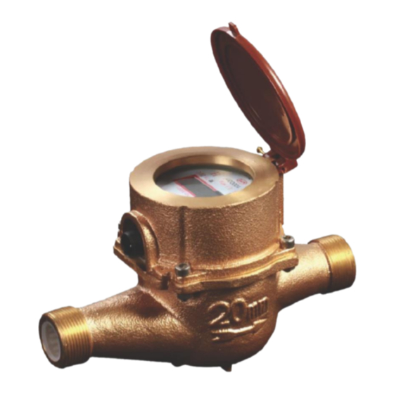
Summary of Contents for DAE INSTRUMENT TH15
- Page 1 TH user manual-1.1e 2010/05 Electronic Multi-jet Water Meter (Non-Magnetic Drive) User Manual DAE Instrument Corp. http://daeinstrument.com/...
-
Page 2: Table Of Contents
TH user manual-1.1e 2010/05 INDEX 1. Electronic Multi-jet Water Meter ....................1 1.1 Internal Structure of Electronic Multi-jet Water Meter ..........1 1.2. Introduction to Electronic Multi-jet Water Meter ............2 1.3. Range of Measurement ....................... 3 2. Installation ............................5 2.1. - Page 3 TH user manual-1.1e 2010/05 TABLE OF FIGURE Figure 1: Internal Structure of Electronic Multi-jet Water Meter ............1 Figure 2: Flow-Direction of Electronic Multi-Jet Water Meter ............2 Figure 3: Dimensions of Electronic Multi-Jet Water Meter ..............4 Figure 4: Side View of 2 Connectors ....................6 Figure 5: Water Meter Connector &...
-
Page 4: Electronic Multi-Jet Water Meter
TH user manual-1.1e 2010/05 1. Electronic Multi-jet Water Meter 1.1 Internal Structure of Electronic Multi-jet Water Meter Figure 1: Internal Structure of Electronic Multi-jet Water Meter 11. Impeller Housing 1.Water Meter Cover 6. Filter 2.Impeller Shaft Bearing 7. Electronic Parts 12. Impeller Housing Case 3.Magnetic Induction Sleeve 8. -
Page 5: Introduction To Electronic Multi-Jet Water Meter
TH user manual-1.1e 2010/05 1.2. Introduction to Electronic Multi-jet Water Meter Electronic Multi-jet Water Meter features the latest measurement technology, Non- Magnetic Drive, with unparalleled metering performance. The (non-magnetic drive) Electronic Multi-Jet Water Meter has sensitive measurement capabilities that account for every drop of potential revenue. -
Page 6: Range Of Measurement
TH user manual-1.1e 2010/05 1.3. Range of Measurement DN (mm) Inch (1/2”) (3/4”) (1”) (1 1/2”) (2”) Class C (m /h) ±2 % 0.03~0.12 0.05~0.2 0.07~0.28 0.2~0.8 0.45~3 Class C ±5 0.015~0.0225 0.025~0.0375 0.035~0.0525 0.1~0.15 0.09~0.225 % Maximum 9999.99999 9999.99999 99999.9999 99999.9999 99999.9999 Reading (m Minimum 0.00001... -
Page 7: Figure 3: Dimensions Of Electronic Multi-Jet Water Meter
TH user manual-1.1e 2010/05 Approx. Diameter Model Length (L) H2(±2) D1(±0.3) Weight mm / inch (kg) 15 (1/2”) TH15 25.8 20(3/4”) TH20 33.0 25(1”) TH25 39.0 40(1 1/2”) TH40 93.8 56.0 3.41 50(2”) TH50 67.6 6.38 【Dimensions of Electronic Multi-Jet Water Meter】... -
Page 8: Installation
TH user manual-1.1e 2010/05 2. Installation Electronic Multi-Jet Water Meter operates by measuring the flow velocity. Please make sure the electronic multi-jet water meter has been properly installed in compliance with the following suggestions so as to achieve precise measurement. 2.1. -
Page 9: Figure 4: Side View Of 2 Connectors
TH user manual-1.1e 2010/05 ◎ 2.1.6. Fixed pipes: Vibrating pipes will decrease the metering accuracy. If the pipes are vibrating, the pipes should be fixed firmly. ◎ 2.1.7. Do not submerge the cable connector in water: The cable connector shall be waterproofed in advanced; it shall not be submerged in water directly, or water meter’s communication function may be damaged. -
Page 10: Electronic Register
TH user manual-1.1e 2010/05 3. Electronic Register Figure 6: Electronic Register 3.1 Symbols and Marks ○ 1 Magnet Symbol: As the water meter is interfered by a magnet, the Magnet Symbol ( ) will appear on LCD. ○ 2 Flow Direction: (▲) means forward flow, while (▼) means reverse flow. NOTE: the Electronic Multi-Jet Water Meter has 3 totalizer calculation modes for users to choose as follows: The totalizer stays unchanged despite the reverse flow. - Page 11 TH user manual-1.1e 2010/05 ○ 5 Serial Number of Type Approval ○ 6 Model: TH represents Electronic Multi-jet Water Meter; 15C means the diameter of the water meter is 15mm. ○ 7 Maximum Reading (m3): This indicates the Maximum Reading of water meter. ○...
-
Page 12: Intelligent Functions
TH user manual-1.1e 2010/05 3.2. Intelligent Functions The LCD register can display 3 modes: Totalizer, Flow Rate and Management Modes. Place a magnet on symbol of the LCD register, and remove it immediately as the magnet symbol appears. LCD will display 3 modes in turn according to Figure 7 as you operate the magnet. -
Page 13: Figure 9: Flow Chart Of Management Mode
TH user manual-1.1e 2010/05 individually. In Management Mode, every function will automatically switch per 4 seconds. The sequence of management functions will be shown as follows: Leak Days(00 - 99) Operation Days(00 - 99) Static Days(00 - 99) Reverse Days(00 - 99) Magnetic Interference Days(00 - 99)... - Page 14 TH user manual-1.1e 2010/05 been operating. When water stops flowing through the water meter, the accumulated value will not turn to 0; when water starts to flow through the water meter again, the accumulation will resume. (3)Static Days (OdAy): This indicates how many days water has stopped flowing through the water meter.
-
Page 15: Maintenance
TH user manual-1.1e 2010/05 4. Maintenance 4.1 Maintenance of Electronic Multi-jet Water Meter ◎4.1.1. Routine Maintenance: 4.1.1.1. Please always have the water meter covered by meter cover to prevent LCD from UV damage. 4.1.1.2. Please mind the Battery Power Shortage Symbol on LCD. 4.1.1.3. - Page 16 TH user manual-1.1e 2010/05 4.1.2.5. Communications Abnormality: 1. Check if the cable connector is loosely connected. 2. Perform loop test on the cable between the water meter and MRI to confirm unimpeded communications. lace the MRI next to the water meter and then examine the communications performance.


Need help?
Do you have a question about the TH15 and is the answer not in the manual?
Questions and answers