
Related Manuals for DAE INSTRUMENT SMB350


Summary of Contents for DAE INSTRUMENT SMB350
- Page 1 SMB350 User’s Manual 2020/05/27 Version : 3.3e DAE Instrument Corp. http://www.DAEinstrument.com/...
- Page 2 SMB350 User’s Manual Page 2...
- Page 3 SMB350 User’s Manual SMB350 User Manual, 2020, May Copyright © 2020 DAE Instrument Corp. All rights reserved. DAE Headquarters 5F, No. 157, Xinhu 1 Road, Neihu District, Taipei 11494, Taiwan, R.O.C. Tel:+886-2-2793-6123 Fax:+886-2-2793-6150 e-mail:info@DAEinstrument.com DAE Controls LLC. 3124 Chesapeake Dr. Sterling Heights, MI 48314, USA Tel:+1-248-635-3708...
- Page 4 This symbol means there is risk of danger. The SMB350 is a sensitive electrical equipment, care should be taken so that the maximum benefit and performance can be derived from the device. Before cleaning or performing any maintenance on the SMB350, disconnect the device from its auxiliary power source.
- Page 5 Do not use any water or other liquid cleaning agents. Ventilation Check to make sure that there is sufficient space around the periphery of the SMB350 to allow air to circulate. Reposition any extraneous wiring that is on the SMB350. Maintenance Check to make sure that the wiring contacts are tight and making good contact, tighten any terminal screws that may have loosened over time from jarring or vibration.
-
Page 6: Table Of Contents
SMB350 User’s Manual CONTENT Introduction ..................... 7 General Description ................7 Features ..................... 7 Certifications ..................7 Specifications ..................8 Product Information ................9 Installation ..................... 11 Front Panel & Terminals ..............12 Terminals Detail ................13 Mounting Procedure ................14 Before Installation ................ -
Page 7: Introduction
PF as well. The SMB350 can be used in 3 phase 4 wire, 3 phase 3 wire and 1 phase 2 wire configurations. The SMB350 offers up to 24 channels when used in 1 phase 2 wire configurations. -
Page 8: Specifications
SMB350 User’s Manual 1.4 Specifications Item Descriptions Common Voltage A/B/C/N SMB350-4 4 channels of 3p4w or 3p3w or 12 channels of 1p2w Channels SMB350-8 8 channels of 3p4w or 3p3w or 24 channels of 1p2w Current Measurement Depends on dedicated CT type ... -
Page 9: Product Information
SMB350 User’s Manual 1.5 Product Information Ordering Code SMB350-8 Ordering Compatible Max. CT Type Remark Code Current SMB350-8-A CT-5D3 Solid-Core Use with 5A output regular CTs CT-5S Split-Core CT ratio depends on specs of regular CTs SMB350-8-B CT-50D3 CT-100D3 100A... - Page 10 SMB350 User’s Manual SMB350-4 Ordering Compatible Max. CT Type Remark Code Current SMB350-4-A CT-5D3 Solid-Core Use with 5A output regular CTs CT ratio depends on specs of regular CTs CT-5S Split-Core Use with 5A output regular CTs SMB350-4-B CT-50D3 CT-100D3...
-
Page 11: Installation
2.01" x 2.64" x 1.34" (51 x 67 x 34mm) 2 Installation The SMB350 is a sophisticated energy meter with multiple capabilities and functions. Before installation be sure to read and understand this section and the appropriate wiring diagrams. Installation of this device must be performed by qualified personnel according to these instructions and in conjunction with all applicable electrical codes. -
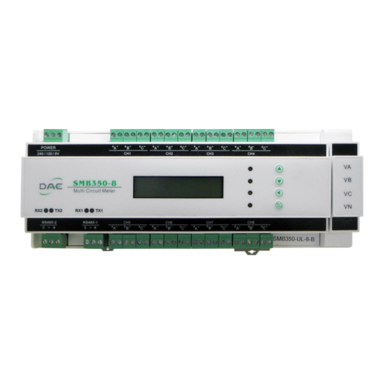
Page 12: Front Panel & Terminals
Channel 7 3-phase current inputs Channel 8 - A, B, C Channel 8 3-phase current inputs Measured voltage terminals - Common voltage for all channels VA, VB, VC, VN Note : Items 19 to 22 are not applicable to the SMB350-4 Page 12... -
Page 13: Terminals Detail
SMB350 User’s Manual 2.2 Terminals Detail Voltage input terminals (Measured voltage input) Use the proper size and wire type as per electrical regulations. Other terminals Make sure that the wires are screwed tightly onto the terminals and making good contact. -
Page 14: Mounting Procedure
SMB350 User’s Manual 2.3 Mounting Procedure Mounting Page 14... -
Page 15: Before Installation
Make sure to turn off all power sources to the SMB350 and any adjacent power sources before performing the installation. 2.5 Meter Installation Mount the SMB350 to the desired DIN rail track location and lock it in place. Attach the dedicated CTs to the CT terminal with their appropriate channels and phases. -
Page 16: Ct Installation
SMB350 User’s Manual 2.6 CT Installation Polaris meters only can use the dedicated CT provided by DAE. DAE’s dedicated CTs have two types as the follow descriptions. Split-core CT installation Load side Step 1. Open the split-core CT Step 2. Hoop up the loading wire Step 3. -
Page 17: Wiring Diagram
Red or white wire to CT+ terminal on the meters, and black wire to CT- terminal on the meters. Please see the “Terminals” section. 2.7 Wiring Diagram All circuits measured by SMB350 must be from the same power source. 3-Phase, 3 Wire ≤ 600VAC... - Page 18 SMB350 User’s Manual 3-Phase, 4 Wire = 80~350VAC Single-Phase, 2 Wire = 80~350VAC Note : Please install fuses for the voltage inputs. Page 18...
-
Page 19: Measuring Multiple Loads With One Channel
The auxiliary voltage is single phase and can be derived from either a 240VAC or 120VAC power source, but not both. The auxiliary power is the working voltage for the SMB350 itself and is electrically isolated from the Page 19... -
Page 20: Using A Regular 5A Output Ct
CT to the dedicated 5A CT as shown in the diagram below. When using regular CT, the SMB350 needs to set the CT ratio. For example, when using 500A : 5A regular CTs, the CT ratio should set 100. -
Page 21: Rs485 Installation
HMI devices such as touch panels, digital intercoms or industrial PCs. Multiple SMB350 may be connected to the same RS485 network (daisy chain). All the positive terminals are to be connected together using the same red conductor, and all the negative terminals are to be connected together to the same blue wire. -
Page 22: Operating And Display
SMB350 User’s Manual 3 Operating and Display 3.1 Preface Each SMB350 meter has several display pages to show different info, settings and measurement parameters of the meter. 3.2 LCD Display The LCD shows the various parameters organized into pages, since the LCD... - Page 23 Phase C PF Phase C PF Phase C PF Channel 2 Channel 4 Channel 6 Channel 8 2-SPF 4-SPF 6-SPF 8-SPF Average PF Average PF Average PF Average PF Note : Channels 5~8 are not applicable to the SMB350-4 Page 23...
-
Page 24: Setup
SMB350 User’s Manual 3.3 Setup The follow parameters can be set on the front panel of SMB350. RS485-1 Address-1 (default = last two digits of the serial number, 00 = 100) RS485-1 Baud rate-1 (default 9600) RS485-2 Address-2 (default = 1) ... -
Page 25: Troubleshooting
4 Troubleshooting The SMB350 multi-circuit meter has been factory calibrated before being packed and shipped and does not require calibration during installation or use. The SMB350 should provide many years of trouble free service if installed and used properly. However, there are times when things do not go as intended and the meter will not work for one reason or another. - Page 26 SMB350 User’s Manual Problems or Symptoms Possible Causes and Solutions The accumulation of kWh does not (a) Check the CT ratio if use with regular 5A output match total consumption. CT. (e.g. 500A : 5A, the CT ratio = 100) (b) Check to make sure the Aux.
-
Page 27: Frequently Asked Questions
Q. How can different types of CTs be used on a single SMB350? A. Different types of CTs may be used on a single SMB350 under certain conditions and with certain limitations, please see the section on “Product Information” for a detailed explanation. - Page 28 (3) Make sure that the baud rate set for SMB350s and the host computer are the same. (4) Make sure that each of the SMB350 on the same bus has its own unique device address. (5) Make sure that the polarities for the RS485 wiring are correct for all the SMB350.
- Page 29 (2) The auxiliary power is available in models for either 120 or 240 VAC. If 120VAC is applied to a 220VAC model, the SMB350 will not be damaged, but it won’t work either. But if 220VAC is applied to a 120VAC model, then the unit will be damaged.
-
Page 30: Warranty And Return Policy
SMB350 User’s Manual 6 Warranty and Return Policy Warranty The warranty is effective for a period of five years from the date of shipment. The buyer must inform DAE of the defect within 80 days after the defect is experienced or found. -
Page 31: Supplementary Information
SMB350 User’s Manual 7 Supplementary Information Please add fuses to the Aux. voltage input and measured voltage input to protect damage from a short circuit. Our contact information US Website: www.DAEcontrols.com US Email: info@DAEcontrols.com US Phone: +1-248-635-3708 International Website: www.DAEinstrument.com International Email: info@DAEinstrument.com... - Page 32 DAE Instrument Corp.
Need help?
Do you have a question about the SMB350 and is the answer not in the manual?
Questions and answers