
Subscribe to Our Youtube Channel
Related Manuals for Murphy EVS EX


Summary of Contents for Murphy EVS EX
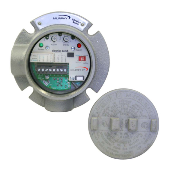
- Page 1 The Murphy™ EVS Model EX Electronic Vibration Switch Installation and Operations Manual 00-02-2003 06-21-10 Section 20...
- Page 2 Good engineering practices, electrical codes, and insurance regulations require that you use independent external protective devices to prevent potentially dangerous or unsafe conditions. Assume that the Murphy EVS system can fail with outputs full on, outputs full off, or that other unexpected conditions can occur.
-
Page 3: Table Of Contents
Table of Contents Table of Contents ........................iii Product Information ........................ 1 EVS Model EX Overview....................1 EVS EX Specifications ....................2 Installation ..........................5 Disassembly and Reassembly ..................5 Mechanical Installation ....................6 ... - Page 4 (THIS PAGE INTENTIONALLY LEFT BLANK)
-
Page 5: Product Information
Stand Alone Switch Both the vibration level and alarm time delay can be set in the EVS EX by adjusting two ports from the front of the switch. The time delay prevents nuisance alarms or shutdowns due to an inadvertent vibration spike. -
Page 6: Evs Ex Specifications
Adjustable set point range and adjustable time delay from 0-10 seconds Relay output Analog option – 4-20mA Output Applications The EVS EX can be used on any equipment where abnormal vibration could lead to equipment damage, including: Cooling towers Reciprocating Compressors... - Page 7 4-20mA Output (Analog Option) Accuracy ± 5% of full scale at 1.5 ips, 100Hz, 21° C (69.8°F) 20 mA corresponds to 1.5 or 3.0 ips peak (factory set) Alarm Level Potentiometer for field adjustable alarm level Alarm level range of 0.1-1.5ips Alarm Trip Time Delay Time delay (for actuation) adjustable from 0 to 10 seconds Output Relay...
- Page 8 Product Dimensions Section 20 00-02-2003 06-21-10 - 4 -...
-
Page 9: Installation
Installation Disassembly and Reassembly Always disconnect the power cord before disassembling. WARNING! Failure to disconnect the power before disassembling may cause personal injury and/or property damage. •Make sure that any disassembly is done in a clean, well ventilated, properly controlled static environment. •Always make sure that the assemblies and sub-assemblies are well supported and insulated when doing any repairs on the instrument. -
Page 10: Mechanical Installation
Mechanical Installation Pre-Installation Requirements Make sure that the surface that you are going to mount the EVS EX to is flat and will fit the hole pattern for the enclosure. If the surface is rough, try to make the surface as smooth as possible. - Page 11 1. Make sure you read the bearing or equipment manufacturers instruction for drilling and tapping equipment casing or housing before installing the EVS EX. 2. Drill and tap four holes for the four (1/4” x 20) bolts that fasten the EVS EX to the equipment casing, bearing housing or mounting plate.
-
Page 12: Cabling And Wiring Installation
Cabling and Wiring Installation Standard EVS S-EX and Analog EVS-A-EX 1. Remove the top cover from the EVS-EX. 2. Place a slotted screw driver in the slot of the 8 pin connector. Pry the screw driver away from the back of the connector until the connector comes loose from the header. 3. - Page 13 4. Put the power cable through the bottom 3/4” NPT opening. (See Teflon Wrapping Technique at the end of this document.) 5. Connect the power cable wires as indicated in the pin out diagrams shown below. Pin out for Standard Switch Pin out for Analog Option 6.
- Page 14 7. Connect the relay wires according to the pin out diagrams above. 8. Reconnect the 8-pin connector by pushing it onto the header until it snaps into place. 9. Thread the conduit connectors into the EVS EX housing until snug. 10. Screw on the top cover until snug.
- Page 15 External Standard Accelerometer Wiring 1. Remove the EVS EX top cover. 2. Connect the Power and Relay wires per instructions above. 3. Place a slotted screw driver in the slot of the 3-pin connector. Pry the screw driver away from the back of the connector until the connector comes loose from the header.
- Page 16 3. Feed the Coaxial cable that leads from the Charge accelerometer through the bottom ¾” NPT opening. 4. You will have to wrap the coaxial cable around the inside diameter of the EVS EX in order to thread the cable connector onto the header. The internal surfaces of the EVS switch enclosure are smooth so there is no fear that the coaxial cable can be damaged.
-
Page 17: Configuration
Configuration Setting the Alarm Threshold WARNING! Always adjust the IPS alarm threshold to meet your specific alarm requirements in the environment the machinery is in. Setting the alarm threshold too high can result in property damage and/or personal injury. 1. Use a small Phillips or slotted head screw driver to adjust the Alarm Threshold IPS setting. - Page 18 3. If you are setting your vibration alarm as a function of the baseline (or a multiple of the baseline), first establish the baseline as follows: Adjust the time delay to the maximum level of 10 seconds. Use a slotted narrow head screw driver and turn the pot clockwise until the indicator is pointing to 1.5 IPS.
-
Page 19: Setting The Delay Setpoint
Setting the Delay Setpoint WARNING! Always adjust the Delay to meet your specific requirements. Too long a delay can result in property damage and/or personal injury. 1. To adjust the Delay setpoint use a slotted narrow head screw driver. 2. Put the screw driver through the adjustment port and into the slot on the top of the delay potentiometer. -
Page 20: Configuring Latching And Non-Latching/Fail-Safe And Normal Modes
Configuring Latching and Non-Latching/Fail-safe and Normal Modes The alarm relays can be configured to operate in a latching or non-latching mode, Fail-safe or Normal mode. Latching Mode – When an alarm or shutdown condition is reached, the output remains in the alarm condition until it is reset. Non-Latching Mode –... - Page 21 The dip switch indicator allows you to select one of four modes by moving the black rectangles to indicate the state of the switch. These modes are illustrated in the following switch configuration examples. Fail-Safe / Latching Mode Fail-Safe / Non-Latching Mode Normal / Non-Latching Mode Normal / Latching Mode Section 20...
-
Page 22: Specifications
Specifications Environmental Temperature: -40° and +85°C (-40° and +185°F) Humidity: 0-95% non-condensing Vibration: 30 g’s max @ 500 Hz External Power Requirement Supply Voltage: 20 - 32 VDC ± 10% Supply Current: 100mA Max Frequency Response 6 to 500 Hz, ±5%, on-board sensor version 6 to 1,000 Hz, ±5%, external sensor version 4-20mA Output (Analog Option) Accuracy ±5% of full scale at 1.5 ips, 100Hz, 21°... -
Page 23: Reset Input
Reset Input Activated by external N.O. relay or push button contact Reset activation time: 0.5 seconds minimum Reset current < 10mA Approvals UL (Pending) CSA (Pending) Teflon Tape 1-2-3 Wrapping Technique The biggest reason for leaks via the conduit into electrical devices is often improper wrapping of the Teflon tape on the threads. - Page 24 If it wants to stop before two turns, DO NOT force the fitting. You can damage the threads or destroy the seal. Do not back off on a tightened fitting or it might leak. 北京卡梅迩控制技术有限公司(前信德迈)2005年开始在中国经销 美国Murphy摩菲仪器仪表产品 地址:北京朝阳区望京SOHO-T1-C 座2115 室 邮编:100102 手机:139 1096 2635 电子邮件:sales@cnmec.biz Section 20...
Need help?
Do you have a question about the EVS EX and is the answer not in the manual?
Questions and answers