Table of Contents
Advertisement
Quick Links
Advertisement
Table of Contents

Related Manuals for Jäger Chopper 2300-40 K S5A


Summary of Contents for Jäger Chopper 2300-40 K S5A
- Page 1 Manual Chopper 2300-40 K S5A High Frequency Spindle Pneumatic taper change...
- Page 2 Identification of HF spindle Spindle type Item no. Serial no. Spindle type Item no..Serial no. Pmax S6-60% S1-100% Rated rotation speed Power data As we always ensure that our HF spindles are at the cutting edge of techno- logical development, we reserve the right to make technical modifications and variations from the exact design described in the manual.
-
Page 3: Table Of Contents
Contents: Translation of the original manual Diameter of media supply line ........ 24 Preliminary information 5 Cooling water.............. 24 Purpose of the manual ............ 5 8.3.1 Quality of cooling water........ 24 Explanation of symbols used .......... 5 8.3.2 Setting the cooling.......... 24 Transport and packaging 6 Compressed air.............. - Page 4 Contents: Translation of the original manual Declaration of Incorporation 39 4 ( 40 ) Item no. 11403003, Revision 12...
-
Page 5: Preliminary Information
Preliminary information Preliminary information The high frequency spindle (HF spindle) is a high quality precision tool for high speed machining. Purpose of the manual The manual is an important component of the HF spindle. Ü Store the manual carefully. Ü Make the manual available to all persons who work with the HF spindle. -
Page 6: Transport And Packaging
Transport and packaging Transport and packaging Avoid strong vibrations or impacts during transportation, as these could dam- age the ball bearings of the HF spindle. Ü Any damage reduces the accuracy of the HF spindle. Ü Any damage restricts the functionality of the HF spindle. Ü... -
Page 7: Designated Use
Designated use Designated use The HF spindle is an “incomplete machine” in accordance with the Machinery Directive and cannot perform any function independently. The HF spindle can only be operated in conjunction with a machine tool and a frequency con- verter. -
Page 8: Safety Instructions
Safety instructions Safety instructions The high frequency spindle is a state of the art product and is safe to operate. However, the HF spindle may pose a risk in the following cases: If it is installed by untrained personnel. If it is used incorrectly. If it is not used in accordance with its intended use. -
Page 9: Safe Working
Safety instructions Safe working Observe all safety instructions set out in the manual, the applicable national accident prevention regulations, and the valid company work, operation, and safety guidelines. DANGER: Due to flying parts. Tools that are not clamped correctly will be flung away by the centrifugal forces that occur during machining. -
Page 10: Shutdown Of Hf Spindle
Safety instructions The tool cutting diameter (X) must not be greater than the maximum clamping range (Y). Ü Always clamp the tool so that it is as short as possible. Ü Keep the dimension (Z) small. Ä (Y) See section: Technical Specifications 14]. -
Page 11: Technical Description Connections Of Hf Spindle
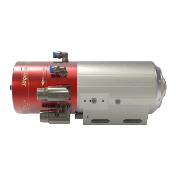
Technical description Technical description Connections of HF spindle Electrical connection for: motor phases Electrical connection for: Tool taper monitoring Cooling water G 1/8" Sealing air Taper cleaning G 1/8" Pneumatic system for tool change G 1/8" Cylinder vent G 1/8" Sound absorber (may only be removed if necessary!) Item no. -
Page 12: Electrical Connection
Technical description Electrical connection The HF spindle may only be operated with a frequency converter (FC). Ü Check whether the current, voltage, and frequency data of the HF spindle match the raw data for the frequency converter. Ü Use a motor supply line that is as short as possible. Ü... -
Page 13: Sealing Air
Technical description Sealing air For guidelines on air quality, The sealing air prevents foreign bodies such as chips and liquids (e.g. emul- see "Air purity classes (ISO sions) from entering the HF spindle. 8573-1) 25]" section. Ü Check that air escapes at the front between the housing and the rotating parts of the HF spindle. - Page 14 Technical Specifications Technical Specifications Bearings Hybrid ball bearing (pcs) Lifetime lubricated maintenance free Power values Pmax./5s S6-60% S1-100% Liquid cooled Rated power [kW] Torque 1,24 0,96 0,82 [Nm] Voltage Current Motor data 3-phase asynchronous drive Motor technology (no brushes or sensors) Frequency 667 Hz Motor poles (pairs)
-
Page 15: Dimensions
Technical Specifications Clamping range up to 10 mm (25/64" ) Clockwise and anticlockwise 9-pin (SpeedTEC) (motor phases) Coupler plug 12-pin (sensors) Weight ~ 7 kg Inner taper run out < 2 µ Axial run-out < 2 µ Dimensions Item no. 11403003, Revision 12 15 ( 40 ) -
Page 16: Technical Data Sheet (Kl 3514, Ac Motor)
Technical Specifications Technical data sheet (KL 3514, AC motor) The power values (S1, S6, S2) Motor type ACM 70/40/50-2 are valid for sinusoidal cur- Rated power 2,3 kW rents and voltages. The power values of the HF Rated rotation speed 40.000 rpm spindle are dependent on the Cooling... -
Page 17: Performance Diagram
Technical Specifications Measured values: S2-Pmax./5 s Rated rotation speed 5,000 10,000 15,000 20,000 25,000 30,000 35,000 40,000 Speed 4,260 8,535 13,470 18,060 23,290 28,360 32,955 38,090 Frequency Rated power 0.45 0.95 1.75 2.333 2.917 Torque 1.01 1.06 1.24 1.23 1.18 1.01 0.75 Voltage... -
Page 18: Wiring Diagram
Technical Specifications Wiring diagram Note: Do not change the ex-works configuration. Any change may cause overvoltage on the electrical components (e.g. PTC, differential magneto resistor). Spindelstecker FS9M (S5) spindle plug FS9M (S5) 0,75 mm² GNYE 0,5 mm² hh:mm *Zähler optional counter optional Stator 0,5 mm²... - Page 19 Technical Specifications output 0,14 mm² 0,14 mm² 0,14 mm² Datum 26.09.23 Projekt Nr.: 29025870 Zeichn.Nr.: Bearb. Perschewski Version Nr.: Gepr. Blatt Pinbelegung FS12M (S34) Norm DIN 81346 Übersetzungen, Vervielfältigungen und die Weitergabe an Dritte, auch nur auszugsweise, ist ohne schriftliche Gehnehmigung der Fa. Nakanishi Jaeger GmbH untersagt Item no.
-
Page 20: Motor Protection Ptc 130°C
Technical Specifications Motor protection PTC 130°C PTC thermistor with protective insulation Characteristic curves for rated response temperatures 90°C to 160°C in accor- dance with DIN VDE V 0898-1-401. Technical Specifications M135 Type = 0 … 40°C) V Max. operating voltage 30 V –... -
Page 21: Speed Sensor (Digital Differential Magneto Resistor)
Technical Specifications Speed sensor (digital differential magneto resistor) Trouble-free evaluation requires good wiring. Ü Use twisted and shielded cables. Ü Connect the HF spindle based on the connection example shown below. Note: Resistor (Rx). If the resistor (Rx*) is already integrated in the evaluation unit (FC): Only connect signal and ground. -
Page 22: Air-Borne Noise Emissions
Operating location Air-borne noise emissions CAUTION: Noise has an impact on health. Only operate the HF spindle if you are wearing hearing protection. Operating location DANGER: Due to flying parts. If the HF spindle is incorrectly attached, it may come loose during operation and be flung away by the forces that occur. -
Page 23: Installation
Installation Installation Before installation: Ü Check the HF spindle for damage and ensure that it is complete. If the HF spindle has been stored for a long period: Ü Carry out all steps in the Commissioning after storage section. Installing the HF spindle Complete the following steps in sequence to install the HF spindle: Ü... -
Page 24: Diameter Of Media Supply Line
Installation Diameter of media supply line Ü The nominal size of the media supply lines can be found in the following table: Medium Compressed air 2.8 mm " 4 mm " Compressed air 4 mm " 6 mm " Compressed air 6 mm "... -
Page 25: Compressed Air
Installation Compressed air 8.4.1 Air purity classes (ISO 8573-1) Class 3 Solid impurities Filter grade at least 5 µm for solids Class 4 Water content Max. pressure dew point +3 °C Class 3 Total oil content Max. oil content 1 mg/m 8.4.2 Setting the sealing air For guidelines on air quality,... -
Page 26: Setting Values
Commissioning 8.4.3 Setting values For guidelines on air quality, Ü Keep to the following values: see "Air purity classes (ISO Pneumatic system for tool change ≥ 6,0 bar 8573-1) 25]" section. Commissioning DANGER: Due to flying parts. If the speed is selected incorrectly, the HF spindle or the tool may be de- stroyed and their fragments may be flung out. -
Page 27: Daily Start-Up
Commissioning Daily start-up Proceed as follows to preheat the grease lubrication of the bearing and to protect it: Ü Operate the HF spindle with a clamped tool (without machining). Ä Approx. 2 minutes. Ä At maximum 50 % of the maximum permissible speed. (See Commissioning 26] section) -
Page 28: Tool Change
Tool change Tool change CAUTION: Danger of being drawn in by rotating shaft. If the shaft is still rotating, fingers and hands may be drawn in and crushed. Only change the tool if the shaft is at a standstill. Note: Ensure functionality. Never operate the HF spindle without a clamped tool shank. -
Page 29: Changing The Tool
Tool change 10.2.1 Changing the tool Note: Ensure concentric run-out quality. Only use tool mounts, clamping nuts, and clamping devices that are bal- anced according to DIN ISO 1940 balance grade G DIN ISO 1940. End face Clamping nut (optional accessory) Collet (optional accessory) Tool Holder... -
Page 30: Maximum Tightening Torques
Tool change 10.2.2 Maximum tightening torques Excessive tightening torques (M ) can damage or destroy the collet, clamping nut, and collet mount of the shaft. Keep to the following values. Ü Short clamping bore Short clamping bore Ä Clamping diameter: 1,0 - 4,5 mm Ä... -
Page 31: Tools For High Speed Cutting
Tools for high speed cutting Tools for high speed cutting DANGER: Due to flying parts. If the wrong direction of rotation is used, the tool is damaged when load is applied. The centrifugal forces cause the broken part to be flung out. Only use tools with the correct direction of rotation for the HF spindle. -
Page 32: Maintenance
Maintenance Maintenance Only specialist personnel may perform maintenance on the spindle. The HF spindle must be shut down before any maintenance work. Ü Make sure that the shaft of the HF spindle has come to an absolute stand- still. Ü Before carrying out any work, read the corresponding section of the man- ual carefully again. -
Page 33: In The Case Of Storage
Maintenance Ü Clean the tool taper. Ü Clean the collet and the collet mount. Ü Apply a light greasy film to the taper of the collet after cleaning. Ä Only use the collet grease from the service set. This improves the sliding movement and increases the clamping force of the collet. -
Page 34: Dismantling
Dismantling Dismantling Proceed as follows to remove the HF spindle: Ü Completely disconnect the power supply. Ü Completely disconnect the media supply (air and liquid). Ü Make sure that the shaft of the HF spindle has come to an absolute stand- still. -
Page 35: Service And Repairs
Service and repairs Service and repairs DANGER: Electric shock. Electric shock can lead to severe burns and life-threatening injuries. Take measures to prevent hazards caused by electrical energy (for details re- fer e.g. to the regulations issued by the VDE and the local energy supply companies). -
Page 36: Malfunctions
Service and repairs 14.2 Malfunctions The list below can be used to quickly investigate and eliminate faults. HF spindle not rotating Cause Troubleshooting Check the frequency converter. Check the machine. Check all electrical connections. power supply Check all wires in the motor cable. Activate the Start/Reset button. - Page 37 Service and repairs HF spindle becomes loud Cause Troubleshooting Only use balanced tools. (Also see the "Tools for high speed cutting [} 31]" section.) Tool unsuitable Check the tool for damage. Replace damaged tool. HF spindle is not Only use spindle holders from the original accessories or clamped truly or is dis- holders produced according to the tolerances specified by torted...
- Page 38 Service and repairs HF spindle vibrates/ Cause Troubleshooting oscillates Only use balanced tools. (Also see the "Tools for high speed cutting [} 31]" section.) Tool unsuitable Check whether the tool is suitable for the application. Check the tool for damage. Replace damaged tool. Remove all contamination between the tool taper and shaft of the HF spindle.
- Page 39 Tel. +49 (0) 60029123 -0 hereby declare that the product, Product High Frequency Spindle Type Chopper 2300-40 K S5A Serial no. See last page of manual as far as possible from the supplied, complies with the essential requirements of the Machinery Directive 2006/42/EC.
- Page 40 Norcross, GA 30071 GERMANY Nakanishi Jaeger YouTube channel Scan this QR code with any QR code +1 (770) 674-4480 +49 (0)6002-9123-0 scanner. sales@anakanishi-jaeger.com office@jaegerspindles.com www.nakanishi-jaeger.com www.nakanishi-jaeger.com/en Serial number Type Chopper 2300-40 K S5A Item no. 11403003 Revision Date 01.09.2023 Language...
Need help?
Do you have a question about the Chopper 2300-40 K S5A and is the answer not in the manual?
Questions and answers