Table of Contents
Advertisement
Quick Links
I
NSTALLATION,
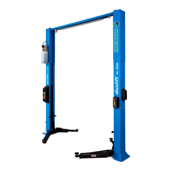
T w o P o s t S u r f a c e M o u n t e d L i f t
3 5 0 0 k g c a p a c i t y
Voltage
400 V
230 V
O
PERATION
S n a p - o n E q u i p m e n t s . r . l .
V i a P r o v . C a r p i , 3 3
4 2 0 1 5 C o r r e g g i o ( R E )
I t a l i a
FAX: +39 0522/733-479
Phone: +39 0522/733-480
Web Site:
www.snapon-equipment.eu
Original Instructions
Frequency
50 Hz
50 Hz
& M
AINTENANCE
M O D E L S
d u o l i f t
d u o l i f t
Phases
3 PH
1 PH
1
M
ANUAL
®
H L 3 5 0 0 S
®
H L 3 5 0 0 T
Power
3.0 kW
3.0 kW
Advertisement
Table of Contents

Subscribe to Our Youtube Channel
Related Manuals for Hofmann duolift HL3500S


Summary of Contents for Hofmann duolift HL3500S
- Page 1 & M NSTALLATION, PERATION AINTENANCE ANUAL T w o P o s t S u r f a c e M o u n t e d L i f t M O D E L S ® d u o l i f t H L 3 5 0 0 S ®...
- Page 2 Manufacturer Snap-on Equipment Hungary Kft. European address: Address Snap-on Equipment Hungary Kft. H-9400 Sopron Somfalvi u. 13. www.snapon-equipment.eu Type of machine Passenger car and light truck 2 post lift Type ® duolift HL3500 Model(s) ® ® duolift HL3500 S/ duolift HL3500 T Manufacturing year 2016...
- Page 3 DECLARATION OF CONFORMITY ATTACH THE FORMAL DECLARATION OF CONFORMITY IN THIS PAGE REV 8-5-2016 HL3500-IOM-B...
-
Page 4: Table Of Contents
CONTENT 1 FOREWORD ................................ 5 2 GENERAL SAFETY AND ACCIDENT-PREVENTION RULES ................5 3 WORKPLACE ENVIRONMENT .......................... 6 4 RESIDUAL HAZARDS ............................7 4.1 CRUSHING HAZARD ............................ 8 4.2 HAZARD OF THE VEHICLE TO FALL FROM THE LIFT ................8 4.3 HAZARD OF OVERTURNING OF THE VEHICLE DUE TO INSTABILITY OF THE LOAD ...... -
Page 5: Foreword
Hofmann declines responsibility for damages to things and/or persons consequences of a negligent use of the lift or to the lack of observance of the instructions contained in this manual. -
Page 6: Workplace Environment
DANGER In order to prevent risks to third parties and/or damages to things, before any operation takes place, the user shall make su In order to prevent risks to third parties and/or damages to things, before any operation takes place, the user shall make su In order to prevent risks to third parties and/or damages to things, before any operation takes place, the user shall make sure that there are not things or persons close to the lift before starting any working cycle. -
Page 7: Residual Hazards
® processes of the Hofmann duolift HL3500 HL3500 two post vehicle lift were carried out by Hofmann Manufacturing Manufacturing with the outmost care and attention to assure compliance of the product with the strictest safety standards through its high me attention to assure compliance of the product with the strictest safety standards through its high mechanical and engineering quality chanical and engineering quality. -
Page 8: Crushing Hazard
4.1 CRUSHING HAZARD This hazard is present during the lowering operation of the lift. DANGER In order to prevent risks to third parties and/or damages to things, before any operation takes place, the user shall make sure that there are no things or persons in the field of motion of lift before and while operating it. -
Page 9: Hazard Of Overturning Of The Vehicle Due To Instability Of The Load
4.3 HAZARD OF OVERTURNING OF THE VEHICLE DUE TO INSTABILITY OF THE LOAD This hazard is present during both the raising and the lowering phases. The user shall make sure that the vehicle correctly is positioned on the arms of the lift, as per the requirements given in § 5,5, and that all the actions are taken at a reduced speed. DANGER Do not raise the lift if the vehicle's weight is not properly balanced on the load supporting devices. -
Page 10: Emergency Stop
DANGER It is not allowed to perform any type of aid and/or maintenance operation to the lift while being operated. DANGER Before operating the lift, make sure that the vehicle to be lifted does not have any fluid leakages. If fluids are spilled on the floor immediately remove them. DANGER Do not wash the vehicle on the lift. -
Page 11: Duolift® Hl3500 Two Post Lift
5.1 DESCRIPTION OF THE LIFT ® Hofmann duolift HL3500 is a two post type lifting device designed for servicing or repairing passenger cars and light commercial trucks with a gross maximum weight of 3500 kg. Any other use of the lift is not allowed, was not considered during the designing phase and could compromise the safety of the lift. - Page 12 Fig. 3, General Specifications & Service Bay Layout REV 8-5-2016 HL3500-IOM-B...
-
Page 13: Layout
Any accessory or part installed on the lift or the vehicle shall be comprised in the compute of the raised weight. For this reason strictly it is ® prohibited to use accessories not specifically designed by prohibited to use accessories not specifically designed by Hofmann for the use on the duolift HL3500 type lift. type lift. -
Page 14: Installation
This lift has been evaluated only for an operating ambient temperature range of 10 – 40°C (41– 104°F). Hofmann does not assume any responsibility for the eventual damages to persons, objects and/or to the lift, caused by use which is inadequate and/or inconsistent with the prescription of this manual. -
Page 15: Storage
DANGER Always load, unload and handle the lift package paying the utmost attention to possible hazards, in particular make sure that there are no persons or things in the range of the lifting device. 5.2.2 STORAGE If the lift, before being unpacked, needs a temporary storage, keep it in a covered dry place. 5.2.3 UNPACKING Once positioned the load close to the point in which the lift shall be installed, remove the eventual packing. -
Page 16: Assembly
Verify that all around the lift there is sufficient space in order to guarantee the correct and safe use of the lift. DANGER ® In order to properly install Hofmann duolift HL3500 type lift, read carefully this Manual first and refer only to somebody qualified by Hofmann for the job. - Page 17 5.3.3.2 LAYOUT AND INSTALLATION Layout the service bay using chalk lines according to the architect’s plans or owner’s instructions ( S e e § 5 . 1 / Fig. 3/ Table 1) . DANGER Failure to install the lift as per the orientation given in §5.1 can result in personal and property damage. Break down crate carefully.
- Page 18 Fig. 7, Overhead Breakdown Assemble overhead subassembly(EAA0431V07A - 1) to idler column using only two of the mounting bolts and allow to pivot until it rests on the idler column (use protection between painted components), see Fig. 8 ONE BOLT ON THE SAME LOCATION OF EACH SIDE, HAND TIGHT ONLY. BOLT: M10X25, 1-14688A;...
- Page 19 Fig. 10, Install the Mounting Bracket Fig. 11, Power Unit Mounting Assemble Power Unit (EAH0065V13A or EAH0065V14A) to Power Column Extension (EAM0119V51A), DO NOT fill with oil at this time, see Fig. 11. Install Bulkhead fitting (EAH0065V21A) onto the power side extension column, then connect the Tee Branch Fitting (EAH0065V22A) with the bulkhead fitting from inside of the power side extension column, see Fig.
- Page 20 Fig. 13, Assemble Hose Assemble Power Side Lock Cover Assembly (EAM0128V03A, SCREW 1-02088A) to power column, see Fig. 13. Assemble overhead Limit Switch assembly (EAA0431V07A - 2) to power column using only two of the mounting bolts and allow pivoting until it rests on the power column (use protection between painted components), see Fig. 14. ONE BOLT ON THE SAME LOCATION OF EACH SIDE, HAND TIGHT ONLY.
- Page 21 Erect or lift Power Column assembly using two men or a mechanical assist such as lift truck or Jeanie Lift. DANGER Make sure that while raising the column, the load is always properly held. To install the lift is preferable to use a crane; using a fork lift is acceptable, but in this case oversized forks shall be installed, positioning them as close as possible to the load Position Power Column on chalk lines from bay layout and confirm V notches are aligning with the CENTER LINE, see Fig.
- Page 22 Fig. 18, Column shimming Hammer in the anchors until they make contact with the base plate. Hand tightens all anchor bolts. Check that the column is level. Adjust shims as required. Tighten all anchors (step 5 of Fig. 16) and recheck column for plumb. Re-shim if necessary. To set anchors, Torque anchors to: If HILTI M16 mechanical anchors are used: initial torque = 80 N·m;...
- Page 23 Fig. 20, Route synchronizing cables REV 8-5-2016 HL3500-IOM-B...
- Page 24 This is not to be considered a defect of the lift; the extent of the effects of a low ambient temperature could be reduced by using lower viscosity oil. Contact Hofmann technical assistance to get information on the most suitable type of oil to be used.
- Page 25 Fig. 23, Lubricate the footpad assembly 5.3.3.4 CONNECTION OF THE ELECTRIC BOX DANGER Do not connect the lift to the electric line before having verified that the line itself is completely compliant to the enforced norm. DANGER Do not connect the lift to the electric line before having verified that there is a properly working grounding circuit and there is a properly working protection circuit.
- Page 26 Mount the Main Control Box (MCB) to Power Side Column. Be sure to use correct Mounting hardware to avoid interference with the internal moving parts of the lift, refer to §9.3. Route electrical wiring harness from power unit through power column to the control access hole. W2 or W12: Pre-wired on POWER UNIT, CG3 →...
- Page 27 Fig. 26, Routing Electrical wiring harness ATTENTION After wiring has been completed, test operation of power unit & overhead limit switch. While raising lift, operate overhead shutoff bar. Power unit motor should stop when shutoff bar is raised. REV 8-5-2016 HL3500-IOM-B...
-
Page 28: Additional Information On The Hydraulic Circuit
5.3.3.5 FINAL ADJUSTMENTS - HYDRAULICS ATTENTION There could be the presence of air in the hydraulic circuit, especially after the first installation or following some maintenance jobs. Pressurize system until cylinders engage carriages and lower to a comfortable working height (Around 300mm) to bleed cylinders. Start with Idler side first. -
Page 29: Owner/Employer's Responsabilities
This is not to be considered a defect of the lift; the extent of the effects of a low ambient temperature could be reduced by using lower viscosity oil. Check §5.6.3 of this manual and contact Hofmann technical assistance to get information on the most suitable type of oil to be used. -
Page 30: Use
DANGER Before and during each working cycle check that the safety devices are working correctly. Stop using the lift and immediately call Hofmann technical department for assistance if they appear not to be working as required. 5.5.1 LOADING OF VEHICLES. -
Page 31: Operating The Lift
5.5.2 OPERATING THE LIFT To start-up the lift, turn the main switch into the ON position. Then the lift can be controlled at power pack side or another side, see Fig. 29. LEFT PANEL, Main control box on power pack side column RIGHT PANEL, Remote control box on another side column (Option) Push the ‘UP’... -
Page 32: Safety Precautions During The Use
For the extraordinary maintenance of the duolift HL3500 type lift, address exclusively to the qualified Hofmann technical support. 5.6.1 PERIODIC CHECKS: DANGER Modifications not authorized in writing by the technical staff of Hofmann could affect the safe use of the lift. REV 8-5-2016 HL3500-IOM-B... -
Page 33: Specific Checks
Check hydraulic system for fluid leaks. Check adapters for damage or excessive wear. Replace as required with genuine Hofmann parts. Check the activation of the Lock Release. When properly adjusted, the idler column lock should rest firmly against the back of the column when engaged and pull clear of the column back when disengaged. -
Page 34: Hydraulic Oil Recommended
WARNING ® Only use original Hofmann Lift spare parts. Only the original Hofmann Lift parts are approved for the specific use on the duolift ® HL3500 type lift. The use of spare parts not approved by Hofmann for the specific use with the duolift HL3500 type lift not only result in termination of the warranty, but could also compromise the safety characteristics of the lift. -
Page 35: Cleaning
5.6.4 CLEANING: For the proper conservation of the system, provide for the regular cleaning of the lift by removing all the dust and/or parts of cloth lost while working. When cleaning, use non-corrosive and non-pollutant detergents that do not react with the paints used on the lift. Use compressed air to clean the power unit. -
Page 36: Technical Assistance
7 TECHNICAL ASSISTANCE The technical service office of Hofmann is always available to answer your questions and satisfy your requests Snap-on Equipment Hungary Kft. Manufacturer Somfalvi u. 13. Sopron 9400 Hungary Address Telephone +36 99 31 30 25 +36 99 31 22 32 email www.snapon-equipment.eu... -
Page 37: Spare Parts: General Instructions
SYMPTOMS CHECK POINT ACTION Lifting over weight limit Lift within rated capacity Motor noise Shortage of hydraulic oil “Top Up” hydraulic oil and bleed air in hose line Defect in hose Replace hose Hydraulic oil leakage Leakage from connections Tighten the loose connection Bad cylinder packing Contact Snap-on Technical assistance Contaminated hydraulic oil... -
Page 38: Parts Breakdown Of Final Assembly
9.1 PARTS BREAKDOWN OF FINAL ASSEMBLY Fig. 31, FINAL ASSEMBLY REV 8-5-2016 HL3500-IOM-B... - Page 39 ITEM # PART # QTY/LIFT DESCRIPTION 1-17188A HEX FLANGE BOLT GB5789-86 M8×20 EAM0128V07A ARM LIMIT PLATE(STOPPER) ON POWER SIDE EAA0431V06A COLUMN ASSEMBLY 1-14788A HEX FLANGE NUT GB/T 6177.1 M10 1-14688A HEX FLANGE BOLT GB 5789-86 M10×25 1-15788A HEX FLANGE NUT GB/T6177.1 M8 1-05388A FLAT WASHER GB/T 95-2002 10 1-05488A...
-
Page 40: Parts Breakdown Of Overhead Assembly
9.2 PARTS BREAKDOWN OF OVERHEAD ASSEMBLY Fig. 32, OVERHEAD ASSEMBLY ITEM # PART # QTY/LIFT DESCRIPTION ITEM # PART # QTY/LIFT DESCRIPTION EAS2172V17A OVERHEAD WELD (END - SECT.) EAM0119V90A STEEL CABLE RING 1-14788A HEX FLANGE NUT GB/T 6177.1 M10 1-02688A M6X12 CROSS RECESS HEAD SCREW GB/T818-2000 EAS2172V16A OVERHEAD WELD (MID - SECT.) -
Page 41: Parts Breakdown Of Parts On Columns
9.3 PARTS BREAKDOWN OF PARTS ON COLUMNS Fig. 33, PARTS ON COLUMNS REV 8-5-2016 HL3500-IOM-B... - Page 42 ITEM # PART # QTY/LIFT DESCRIPTION 1-02088A CROSS RECESS HEAD SCREW GB/T818-2000 M5X8 EAM0128V03A LOCK COVER EAE0070V02A ELECTROMAGNER 1-01988A FLAT WASHER GB/T 95-2002 5 1-02588A CROSS RECESS HEAD SCREW GB/T818-2000 M5X10 1-02288A CROSS RECESS HEAD SCREW GB/T818-2000 M4X12 1-03188A FLAT WASHER GB/T95-2002 4 EAM0119V44A ELECTROMAGNER BRACKET EAM0119V42A...
-
Page 43: Parts Breakdown Of Hydraulic System
9.4 PARTS BREAKDOWN OF HYDRAULIC SYSTEM Fig. 34, HYDRAULIC SYSTEM ITEM # PART # QTY/LIFT DESCRIPTION EAH0065V19A 90 DEGREE FITTING EAH0065V18A END STRAIGHT COUPLING EAH0065V01A CYLINDER ASSEMBLY EAH0065V29A HYDRAULIC HOSE L=3665 WITH 90° ELBOW HOSE FITTING EAH0065V20A FITTING ON PUMP EAH0065V28A PUMP OUTPUT HOSE ASSEMBLY EAH0065V21A... -
Page 44: Parts Breakdown Of Synchronizing System
9.5 PARTS BREAKDOWN OF SYNCHRONIZING SYSTEM Fig. 35, SYNCHRONIZING SYSTEM ITEM # PART # QTY/LIFT DESCRIPTION 1-00187 RESTRAINING RING GB/T 894.1 25 EAM0128V12A PROTECT PLATE FOR THE LOW PULLY EAA0431V14A SHEAVE ASSEMBLY-METAL 1-16088A 1/2-20NF HEX NUT 1-16188A 1/2-20NF HEX JAM NUT 1-08189A EQUALIZING CABLE EAM0119V78A... -
Page 45: Parts Breakdown Of Carriages And Arms
9.6 PARTS BREAKDOWN OF CARRIAGES AND ARMS Fig. 36, CARRIAGES AND ARMS REV 8-5-2016 HL3500-IOM-B... - Page 46 ITEM # PART # QTY/LIFT DESCRIPTION EAM0119V65A LOAD PAD SCREW EAS2172V19A LOAD PAD WELDMENT EAM0119V61A LOAD RUBBER PAD 1-15288A PHILIPS HEAD SCREW GB/T819.1-2000 M6×16 EAS2172V07A FRONT PAD ARM WELDMENT 1-03987A SPRING PIN GB/T879.1-2000 12×60 EAS2172V06A MIDDLE ARM WELDMENT EAM0119V66A LIMIT RING 1-04087A SPRING PIN GB/T879.1-2000 12×80 EAS2172V21A...
-
Page 47: Safety Pictograms On The Lift
ATTENTION Replace all worn or broken parts with genuine Hofmann parts. Contact your local Snap-on parts distributor for pricing and availability. Call Hofmann. at +39 0522/733-411 for the distributor in your area. 10 SAFETY PICTOGRAMS ON THE LIFT For your safety, and the safety of others, read and understand all of the safety notices and decals included here. - Page 48 Do not attempt to raise a vehicle on the lift until the lift has been correctly installed and adjusted as described in this manual WARNING DO NOT operate the lift until its installation has been approved by a Technician authorized by Hofmann. DANGER Do not overload for any reason the lift.
-
Page 49: Initial Check Lists
11 INITIAL CHECK LISTS 11.1 CHECK PROCEDURE FOR LIFT Type of machine Passenger car and light truck 2 post lift ® ® Model(s): duolift HL3500 S/ duolift HL3500 T Serial Number: ® Type: duolift HL3500 Manufacturing year: 2016 Manufacturer: Snap-on Equipment Hungary Kft. European address: Address: Snap-on Equipment Hungary Kft. -
Page 50: Annual Checks
11.2 ANNUAL CHECKS Check report This report is record of all audits for operation conducted and recorded by an inspector or expert. This lift was audited on DATE: ______________________________ and subjected to testing for operational readiness. Describe deficiencies found (if any) Extent of the Check: Pending Checks (if any): If there are (no*) concerns to limit this lift for operation. - Page 51 Check report This report is record of all audits for operation conducted and recorded by an inspector or expert. This lift was audited on DATE: ______________________________ and subjected to testing for operational readiness. Describe deficiencies found (if any) Extent of the Check: Pending Checks (if any): If there are (no*) concerns to limit this lift for operation.
- Page 52 Check report This report is record of all audits for operation conducted and recorded by an inspector or expert. This lift was audited on DATE: ______________________________ and subjected to testing for operational readiness. Describe deficiencies found (if any) Extent of the Check: Pending Checks (if any): If there are (no*) concerns to limit this lift for operation.
- Page 53 Check report This report is record of all audits for operation conducted and recorded by an inspector or expert. This lift was audited on DATE: ______________________________ and subjected to testing for operational readiness. Describe deficiencies found (if any) Extent of the Check: Pending Checks (if any): If there are (no*) concerns to limit this lift for operation.
- Page 54 Check report This report is record of all audits for operation conducted and recorded by an inspector or expert. This lift was audited on DATE: ______________________________ and subjected to testing for operational readiness. Describe deficiencies found (if any) Extent of the Check: Pending Checks (if any): If there are (no*) concerns to limit this lift for operation.
- Page 55 Check report This report is record of all audits for operation conducted and recorded by an inspector or expert. This lift was audited on DATE: ______________________________ and subjected to testing for operational readiness. Describe deficiencies found (if any) Extent of the Check: Pending Checks (if any): If there are (no*) concerns to limit this lift for operation.
- Page 56 Check report This report is record of all audits for operation conducted and recorded by an inspector or expert. This lift was audited on DATE: ______________________________ and subjected to testing for operational readiness. Describe deficiencies found (if any) Extent of the Check: Pending Checks (if any): If there are (no*) concerns to limit this lift for operation.
- Page 57 Check report This report is record of all audits for operation conducted and recorded by an inspector or expert. This lift was audited on DATE: ______________________________ and subjected to testing for operational readiness. Describe deficiencies found (if any) Extent of the Check: Pending Checks (if any): If there are (no*) concerns to limit this lift for operation.
- Page 58 Check report This report is record of all audits for operation conducted and recorded by an inspector or expert. This lift was audited on DATE: ______________________________ and subjected to testing for operational readiness. Describe deficiencies found (if any) Extent of the Check: Pending Checks (if any): If there are (no*) concerns to limit this lift for operation.
- Page 59 Check report This report is record of all audits for operation conducted and recorded by an inspector or expert. This lift was audited on DATE: ______________________________ and subjected to testing for operational readiness. Describe deficiencies found (if any) Extent of the Check: Pending Checks (if any): If there are (no*) concerns to limit this lift for operation.
- Page 60 Check Report Summary Description Date and Name REV 8-5-2016 HL3500-IOM-B...
-
Page 61: Electrical Diagram
12 ELECTRICAL DIAGRAM 12.1 WIRING DIAGRAM FOR THREE PHASES (SHEET 1/3) -
Page 62: Wiring Diagram For Single Phase
12.2 WIRING DIAGRAM FOR SINGLE PHASE (SHEET 2/3) -
Page 63: Wiring Diagram Of Control Boxes
12.3 WIRING DIAGRAM OF CONTROL BOXES (SHEET 3/3) -
Page 64: Wiring Diagram Of The Electrical System
12.4 WIRING DIAGRAM OF THE ELECTRICAL SYSTEM... -
Page 65: Wiring Diagram Of The Electrical System (With / Without Remote Control Box)
12.5 WIRING DIAGRAM OF THE ELECTRICAL SYSTEM (WITH / WITHOUT REMOTE CONTROL BOX) -
Page 66: Electrical Parts Of Main Control Box
12.6 ELECTRICAL PARTS OF MAIN CONTROL BOX Description EAE0070V22A TRANSFORMER JBK3-250VA 230、400VAC/24VAC EAE0066T27A Relay base PYF08A-E 2 EAE0066T26A Relay base PYF14A-E 4 EAE0066T15A Relay MY2NJ-D2 EAE0066T14A Relay MY4N-D2-J DC24V EAE0066T13A TIME RELAY EAE0066T02A limit switch TZ-8108 EAE0070V46A Relay LY2N-D2-J DC24 10A EAE0070V45A Relay base PTF08A-E EAE0066T24A... -
Page 67: Foundation Plan
13 FOUNDATION PLAN ATTACH AN A3 DRAWING...
Need help?
Do you have a question about the duolift HL3500S and is the answer not in the manual?
Questions and answers