Advertisement
Advertisement
Table of Contents

Related Manuals for Lithium Grim Snail Gear

Summary of Contents for Lithium Grim Snail Gear
- Page 1 Snail Gear Building instructions v3.1...
-
Page 2: Table Of Contents
Snail Gear v3.1 Table of contents Components ............................3 PCB layout ............................... 4 General building tips ..........................5 Biasing ..............................5 Off board wiring ............................6 Troubleshooting ............................7 Schematic ..............................8 Read this entire manual thoroughly before you start to building the effect! Especially the Modification and Biasing part. -
Page 3: Components
Snail Gear v3.1 Components Name Value Comment SMF/MKT/FKP2 SMF/MKT/FKP2 SMF/MKT/FKP2 Electrolytic 25V+ Electrolytic 25V+ Electrolytic 25V+ Electrolytic 25V+ Electrolytic 25V+ 470n Electrolytic 25V+ SMF/MKT/FKP2 SMF/MKT/FKP2 Electrolytic 25V+ Electrolytic 25V+ Electrolytic 25V+ Electrolytic 25V+ Electrolytic 25V+ SMF/MKT/FKP2 Electrolytic 25V+ 100u Electrolytic 25V+... -
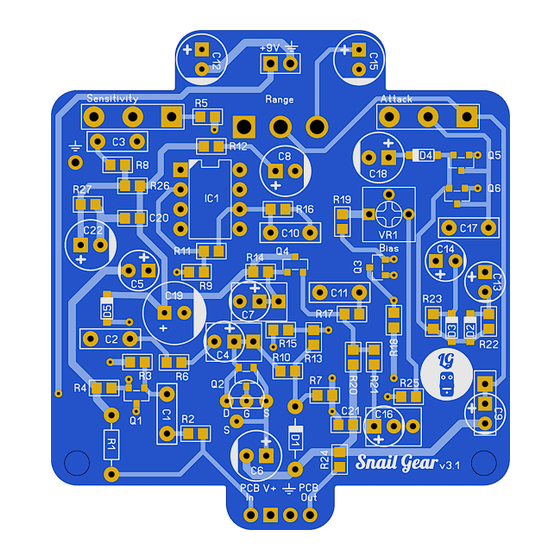
Page 4: Pcb Layout
Snail Gear v3.1 PCB layout... -
Page 5: General Building Tips
Snail Gear v3.1 General building tips Soldering this board can be very complicated for some people since the solder pads are very close together. Use a magnifying glass to make the job easier. Start by soldering the diodes and resistor. R1 is an optional Pull down resistor to prevent a pop when switching the effect on. -
Page 6: Off Board Wiring
Snail Gear v3.1 Off board wiring Ring Output Jack Sleeve R led Sleeve Input Jack The LEDs requires a resistor (R led in the diagram) depending on the type of LED you are using. To be safe use a 3k3 or 4k7 resistor. -
Page 7: Troubleshooting
Snail Gear v3.1 Troubleshooting All PCB’s have been 100% factory e-tested and out of every batch I receive I build a effect to double check, so there should not be a connection problem on the PCB itself. The board is not working (at all), what now? •... -
Page 8: Schematic
Snail Gear v3.1 Schematic...
Need help?
Do you have a question about the Snail Gear and is the answer not in the manual?
Questions and answers